RAK11160 WisDuo LoRaWAN + BLE + Wi-Fi Module Quick Start Guide
This guide covers the following topics:
Prerequisites
Before going through the steps of installing the RAK11160 WisDuo LPWAN Module, make sure to prepare the necessary items listed below.
Hardware
- RAK11160 WisDuo LPWAN+BLE+Wi-Fi Module
- Computer
- USB to UART TTL adapter
Software
- Download and install the Arduino IDE.
For Windows 10 users: DO NOT install the Arduino IDE from the Microsoft App Store. Instead, install the original Arduino IDE from the Arduino official website. The Arduino app from the Microsoft App Store has problems using third-party Board Support Packages.
- Add RAK11160 as a supported board in Arduino IDE by updating Board Manager URLs in Preferences settings of Arduino IDE with this JSON URL
https://raw.githubusercontent.com/RAKWireless/RAKwireless-Arduino-BSP-Index/main/package_rakwireless.com_rui_index.json. After that, add RAKwireless RUI SMT32 Boards via Arduino board manager. - RAK Serial Port Tool
Product Configuration
RAK11160 as a Stand-Alone Device Using RUI3
This section of the guide covers the following:
- Hardware Setup and Access to IO pins of RAK11160
- LoRaWAN OTAA and ABP Example with Arduino IDE
- Wi-Fi Example with RUI3 API
Hardware Setup
The RAK11160 requires a few hardware connections to function properly. The bare minimum requirement is to have the power section properly configured, along with the reset pull-up resistor, antennas, SWD pins, BOOT pin (for recovery), and UART connection for AT commands and firmware updates. Additionally, a USB-UART chip can be included for USB connectivity (optional).
 Figure 1: RAK11160 schematic
Ensure the antennas are properly connected for a strong LoRa and BLE signal. Note that powering the module without an antenna connected to the IPEX MHF4 connectors can damage the RF section of the chip.
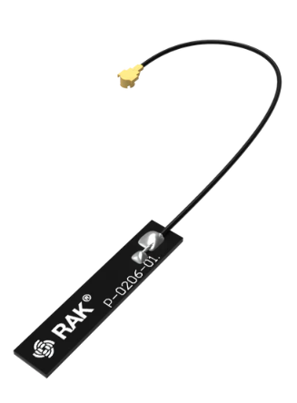 Figure 1: LoRa antenna
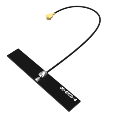 Figure 1: Wi-Fi/BLE antenna
RAK11160 has a label on its sticker indicating where to connect the antennas, as illustrated in Figure 4.
 Figure 1: RAK11160 antenna label
- Detailed information about the RAK11160 LoRa IPEX MHF4 antenna can be found on the 863-870 MHz antenna datasheet or the 902-928 MHz antenna datasheet.
- If the RAK11160 is not an IPEX MHF4 variant, the connection to the antennas are done via the RF pins. RAKwireless offers RF Antenna Design Service for custom PCB designs.
- Standard IPEX connector will not work on RAK11160. The IPEX antenna connectors of RAK11160 are a different variant called IPEX MHF-4. This is specially designed for low-profile circuit boards with limited spaces.
- When using the LoRa, Wi-Fi or Bluetooth Low Energy transceivers, make sure that the antennas are connected. Using these transceivers without an antenna can damage the module.
Software Setup
The default firmware of the RAK11160 is based on RUI3, which allows you to develop your own custom firmware to connect sensors and other peripherals to it. To develop your custom firmware using the Arduino IDE:
- Add RAKwireless RUI STM32 Boards to the Arduino board manager, which will be discussed in this guide.
- Use RUI3 APIs for your intended application.
- Send AT commands and upload custom firmware via UART or wirelessly via BLE.
The AT commands in RAK11160 are still available even if you compile custom firmware via RUI3, and there is an option to disable them.
RAK11160 RUI3 Board Support Package in Arduino IDE
If you don't have an Arduino IDE yet, download it on the Arduino official website.
For Windows 10 and up users: If you installed the Arduino IDE from the Microsoft App Store, uninstall it and reinstall the IDE from the Arduino official website. The version from the Microsoft App Store has issues with third-party Board Support Packages.
After successfully installing the Arduino IDE, configure it to add the RAK11160 to its board selection by following these steps:
- Open Arduino IDE and go to File > Preferences.
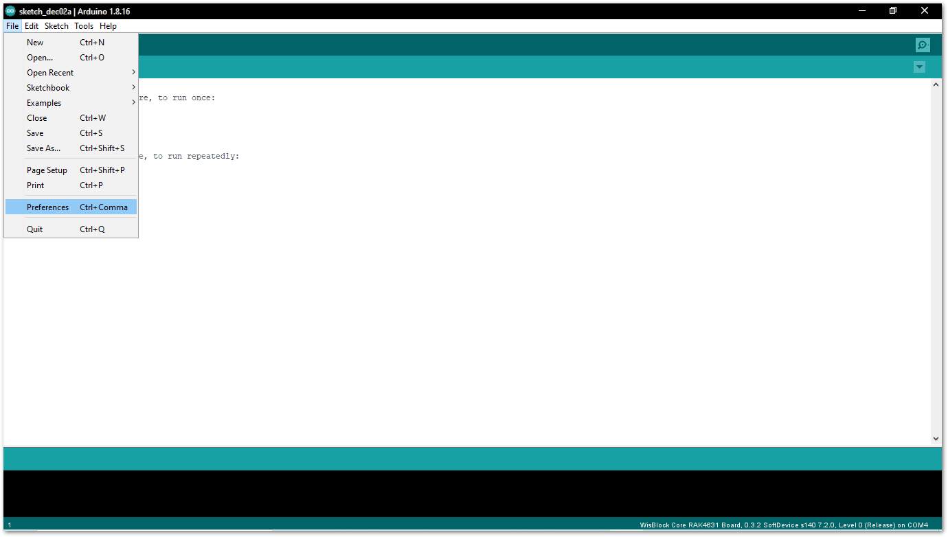 Figure 1: Arduino Preferences
- To add the RAK11160 to your Arduino Boards list, edit the Additional Board Manager URLs and click the icon, as shown in Figure 6.
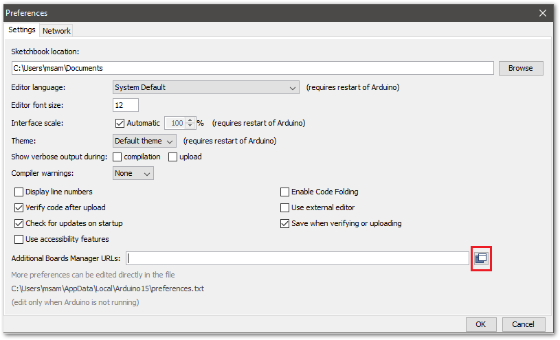 Figure 1: Modify Additional Board Manager URLs
- Copy the URL
https://raw.githubusercontent.com/RAKWireless/RAKwireless-Arduino-BSP-Index/main/package_rakwireless.com_rui_index.jsonand paste it on the field. If other URLs are already there, just add them on the next line. After adding the URL, click OK.
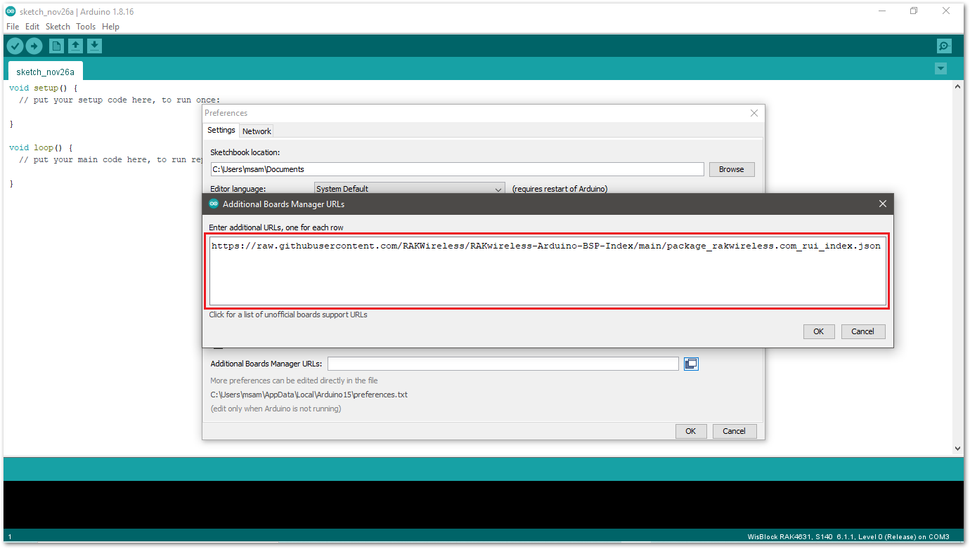 Figure 1: Add Additional Board Manager URLs
- Restart the Arduino IDE.
- Open the Boards Manager from the Tools menu.
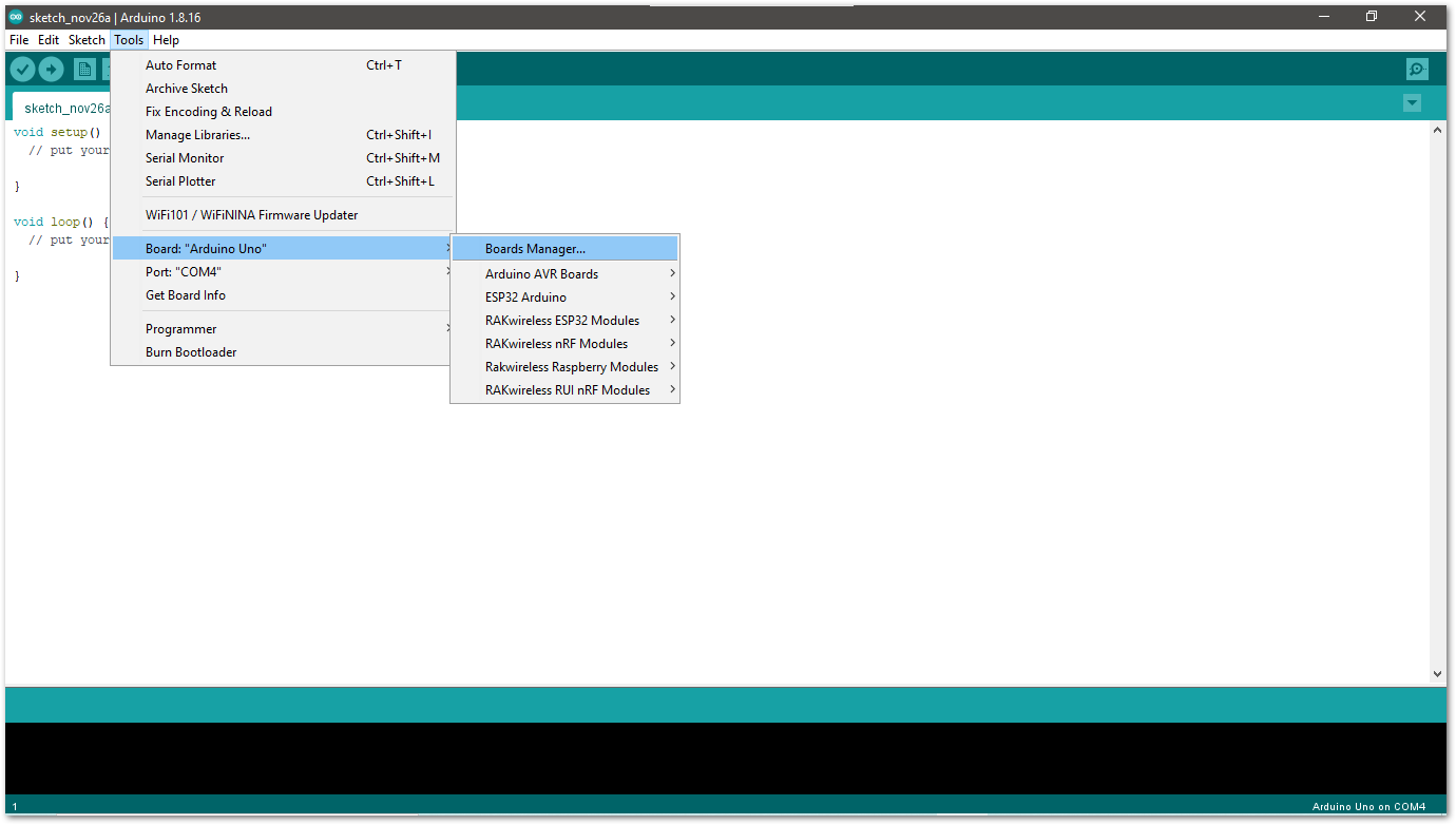 Figure 1: Open the Arduino Boards Manager
- Write
RAKin the search bar, as shown in Figure 9. This will display the available RAKwireless module boards that can be added to your Arduino board list. Select and install the latest version of the RAKwireless RUI STM32 Boards.
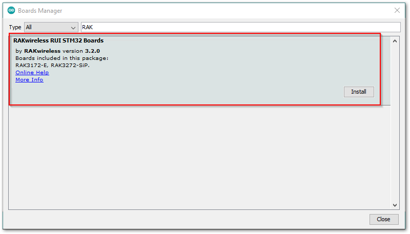 Figure 1: Install RAKwireless RUI STM32 boards
- Once the BSP is installed, select Tools > Boards Manager > RAKwireless RUI STM32 Modules > WisBlock Core RAK11160 Board.
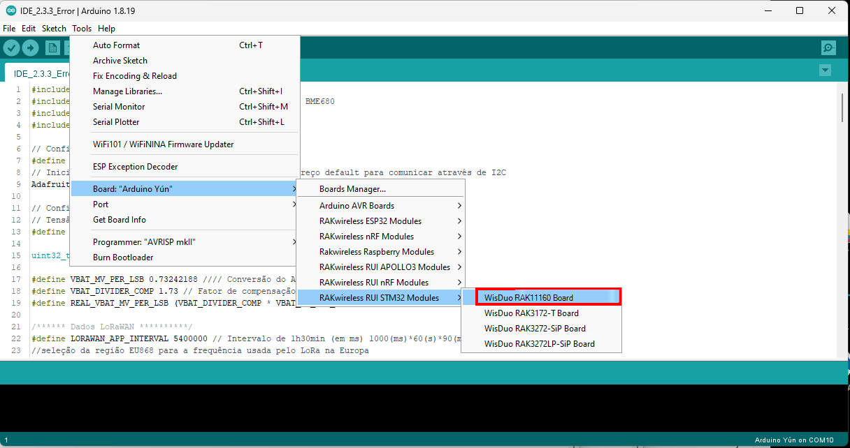 Figure 1: Select RAK11160 Module
Compile an Example with Arduino
- After adding the RAK11160 to the Arduino IDE, test your setup by running a simple program.
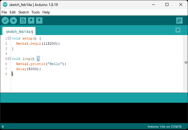 Figure 1: RAK11160 Test
- Connect the RAK11160 via USB and check the RAK11160 COM port using Windows Device Manager. Double-check the USB cable and USB port if the module is not detected.
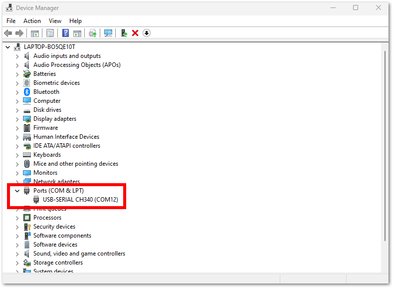 Figure 1: Device Manager Ports (COM & LPT)
- Choose RAK11160 in the board selection by navigating to Tools > Boards Manager and choosing RAKwireless RUI STM32 Modules > WisBlock Core RAK11160 Board.
Figure 1: Select RAK11160 module- Open the Tools menu and select a COM port. COM27 is currently used.
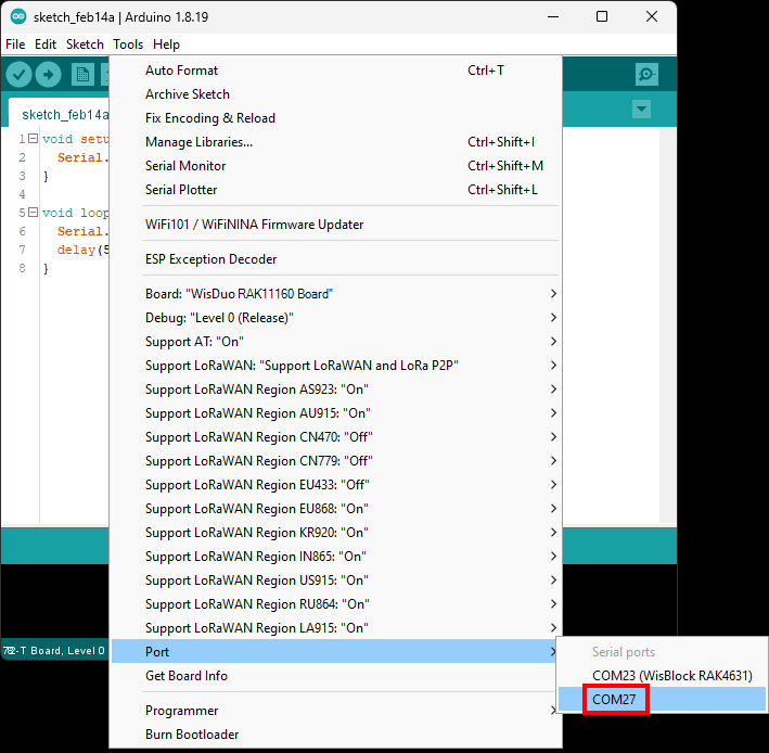 Figure 1: Select COM port
- Click on the Serial Monitor icon to connect to the COM port.
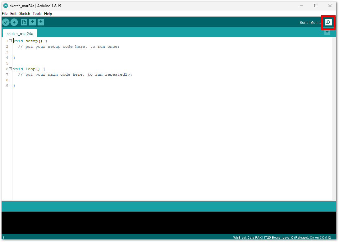 Figure 1: Open Arduino serial monitor
- Once connected to the COM port, send AT commands to the RAK11160. For example, to check the RUI version, type
AT+VER=?in the text field and press Send, as shown in Figure 16.
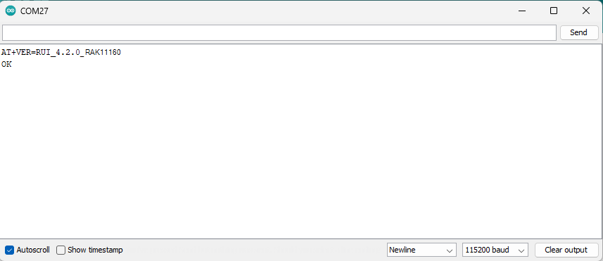 Figure 1: Arduino serial monitor COMx
- Copy the example code below and paste it into Arduino IDE.
Click to view the example code.
void setup() {
  Serial.begin(115200);
}

void loop() {
  Serial.println("Hello");
  delay(5000);
}
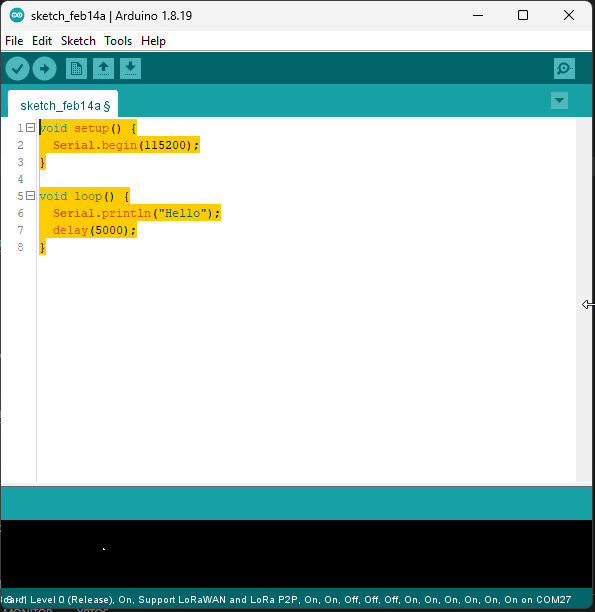 Figure 1: Example code
- Click the Verify button to compile and check for errors.
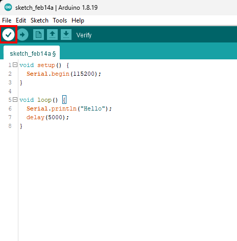 Figure 1: Verify the example code
- When the compilation is complete, click the Upload button to flash the firmware to the RAK11160.
 Figure 1: Upload the example code
- Upon successful upload, the Device programmed message will appear.
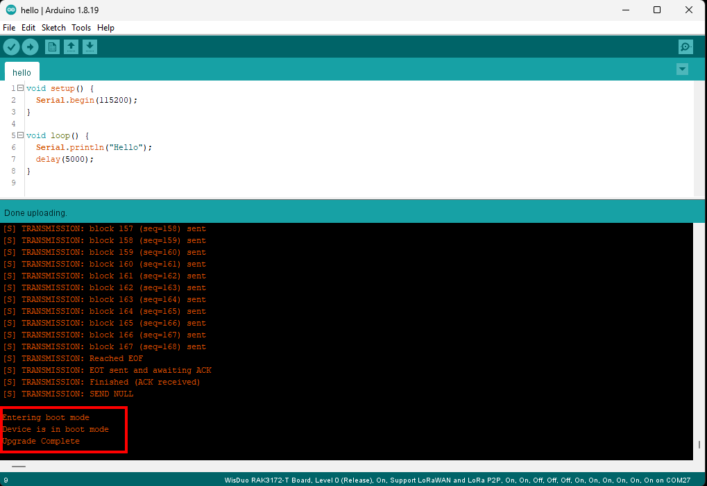 Figure 1: Device Programmed
- The RAK11160 should automatically enter BOOT mode when firmware is uploaded via the Arduino IDE.
- If it does not, BOOT mode can be manually activated by sending the
AT+BOOTcommand. In BOOT mode, standard AT commands will no longer work unlessAT+RUNis sent to exit BOOT mode.
- After the Device Programmed is completed, you will see the "Hello" message every 5 seconds in the console.
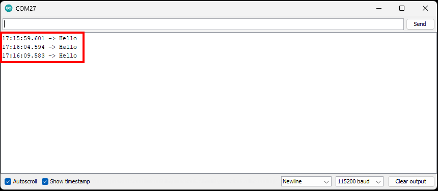 Figure 1: Application log output
RAK11160 IO Pins and Peripherals
This section discusses how to use and access the pinouts of the RAK11160 using RUI3 APIs. It shows basic code for using digital IO, analog input, UART, and I2C.
RAK11160 Digital IO Pins
Available Digital IO Pins in RAK11160
| Pad | GPIO |
|---|---|
| 3 | ST_PA8 |
| 4 | ST_PA9 |
| 7 | ST_PB2/ST_A2 |
| 8 | ST_PB12 |
| 9 | ST_PA10/ST_A3 |
| 14 | ST_PA15/ST_A4 |
| 32 | ST_PB3/ST_A0 |
| 33 | ST_PB4/ST_A1 |
| 34 | ST_PB5 |
| 35 | ST_PA1 |
The GPIO pins of the ESP8684 cannotbe controlled by the STM32WLE5 directly.
Any of the pins listed in the table above can be used. Pins with specific functions, such as UART and I2C, are also usable but with limitations. Those dedicated pins have been excluded from this illustration of digital IO pins.
Click to view the example code.
/*
 RAK11160 Digital I/O Example

 You can use any of the following as Digital I/O:

ST_PA8    PA8
ST_PA9    PA9
ST_PB2    PB2
ST_PA10   PA10
ST_PB12   PB12
ST_PB3    PB3
ST_PB4    PB4
ST_PB5    PB5
ST_PA1    PA1
ST_PA15   PA15
*/

void setup()
{
  pinMode(PA8, OUTPUT); //Change the PA8 to any digital pin you want. Also, you can set this to INPUT or OUTPUT
}

void loop()
{
  digitalWrite(PA8,HIGH); //Change the PA8 to any digital pin you want. Also, you can set this to HIGH or LOW state.
  delay(1000); // delay for 1 second
  digitalWrite(PA8,LOW); //Change the PA8 to any digital pin you want. Also, you can set this to HIGH or LOW state.
  delay(1000); // delay for 1 second
}
RAK11160 Analog Input Pins
Available Analog input Pins in RAK11160
| Pad | Analog in |
|---|---|
| 32 | ST_A0 |
| 33 | ST_A1 |
| 7 | ST_A2 |
| 9 | ST_A3 |
| 14 | ST_A4 |
Any of the pins shown in the table above can be used as an Analog Input Pin. See the example code below.
Click to view the example code.
/*
RAK11160 Analog Input Pins

ST_PB5    PB5
ST_PA10   PA10
ST_PB3    PA3
ST_PB4    PB4

*/

#define analogPin PB5  // or you can use PB5

int val = 0;  // variable to store the value read

void setup()
{
  Serial.begin(115200);
}

void loop()
{
  val = analogRead(analogPin);  // read the input pin
  Serial.println(val);          // debug value
}
RAK11160 Serial Interface Peripherals
- UART
There is one UART peripheral available on the RAK11160. There are also different Serial Operating Modes possible in RUI3, namely AT Mode, and Custom Mode.
| Serial Port | Serial Instance Assignment | Default Mode |
|---|---|---|
| UART0 (Pin 41 - PA3)/(Pin 0 - PA2) | Serial | AT Command |
Click to view the example code.
void setup()
{
  Serial.begin(115200);                   // By default Serial is used for FW update and AT command.
}

void loop()
{
  Serial1.println("RAK11160 TEST!");
  delay(1000); // delay for 1 second
}
- I2C
| I2C | Pad | GPIO |
|---|---|---|
| SDA | 10 | PA11 |
| SCL | 11 | PA12 |
Make sure you have an I2C device connected to the specified I2C pins to run the example code below.
Click to view the example code.
#include <Wire.h>

void setup()
{
  Wire.begin();

  Serial.begin(115200);
  while (!Serial);
  Serial.println("\nI2C Scanner");
}

void loop()
{
  byte error, address;
  int nDevices;

  Serial.println("Scanning...");

  nDevices = 0;
  for(address = 1; address < 127; address++ )
  {
    // The i2c_scanner uses the return value of
    // the Write.endTransmisstion to see if
    // a device did acknowledge to the address.
    Wire.beginTransmission(address);
    error = Wire.endTransmission();

    if (error == 0)
    {
      Serial.print("I2C device found at address 0x");
      if (address<16)
        Serial.print("0");
      Serial.print(address,HEX);
      Serial.println("  !");

      nDevices++;
    }
    else if (error==4)
    {
      Serial.print("Unknown error at address 0x");
      if (address<16)
        Serial.print("0");
      Serial.println(address,HEX);
    }
  }
  if (nDevices == 0)
    Serial.println("No I2C devices found\n");
  else
    Serial.println("done\n");

  delay(5000);           // wait 5 seconds for next scan
}
- SPI
| SPI | Pad | GPIO |
|---|---|---|
| NSS | 42 | PA4 |
| SCK | 43 | PA5 |
| MISO | 44 | PA6 |
| MOSI | 45 | PA7 |
LoRaWAN Example
This example illustrates how to program the RAK11160 as a stand-alone LoRaWAN end-device via RUI3 Arduino APIs. To use RAK11160 as a LoRaWAN end-device, it must be within reach of a working LoRaWAN gateway registered to a LoRaWAN network server (LNS) or with a built-in network server.
If you are new to LoRaWAN, here are a few good references about LoRaWAN and gateways:
To enable the RAK11160 module as a LoRaWAN end-device, a device must first be registered with the LoRaWAN network server. This guide covers both TTN and ChirpStack LoRaWAN network servers and the associated Arduino codes and AT commands for the RAK11160.
- TheThingsNetwork Guide: How to login, register new accounts, and create new applications on TTN.
- RAK11160 TTN OTAA Guide: How to add OTAA device on TTN and what AT commands to use on RAK11160 OTAA activation.
- RAK11160 TTN ABP Guide: How to add ABP device on TTN and what AT commands to use on RAK11160 ABP activation.
- ChirpStack Guide: How to create new applications on ChirpStack.
- RAK11160 ChirpStack OTAA Guide: How to add OTAA device to ChirpStack and what AT commands to use on RAK11160 OTAA activation.
- RAK11160 ChirpStack ABP Guide: How to add ABP device on ChirpStack and what AT commands to use on RAK11160 ABP activation.
Connect with The Things Network (TTN)
This section shows how to connect the RAK11160 module to the TTN platform.
A working gateway connected to TTN is required, or the device must be within the coverage of a TTN community network.
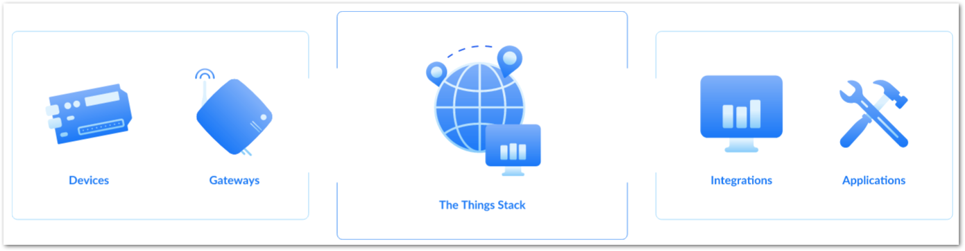 Figure 1: The Things Stack
As shown in Figure 22, The Things Stack (TTN V3) is an open-source LoRaWAN network server suitable for global, geo-distributed public and private deployments as well as for small local networks. The architecture follows the LoRaWAN Network Reference Model for standards compliance and interoperability. This project is actively maintained by The Things Industries.
LoRaWAN is a protocol for low-power wide-area networks. It allows large-scale Internet of Things deployments where low-powered devices efficiently communicate with internet-connected applications over long-range wireless connections.
The RAK11160 WisDuo module can be part of this ecosystem as a device, and the objective of this section is to demonstrate how simple it is to send data to The Things Stack using the LoRaWAN protocol. To achieve this, the RAK11160 WisDuo module must be located within the coverage of a LoRaWAN gateway connected to The Things Stack server.
- Sign up for a TTN account.
a. Go to The Things Network and click on Sign up.
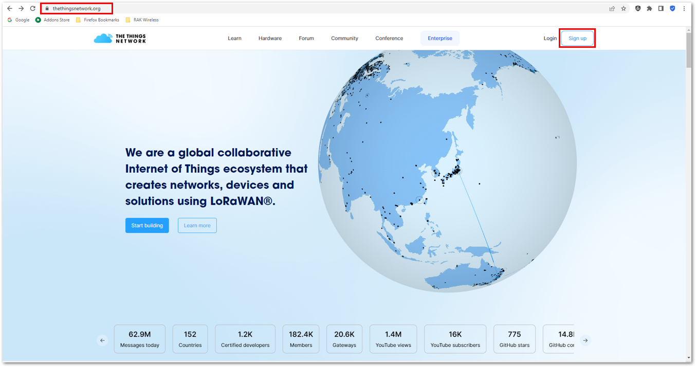 Figure 1: Sign up an account in TTN
b. Select a community type by clicking Get started.
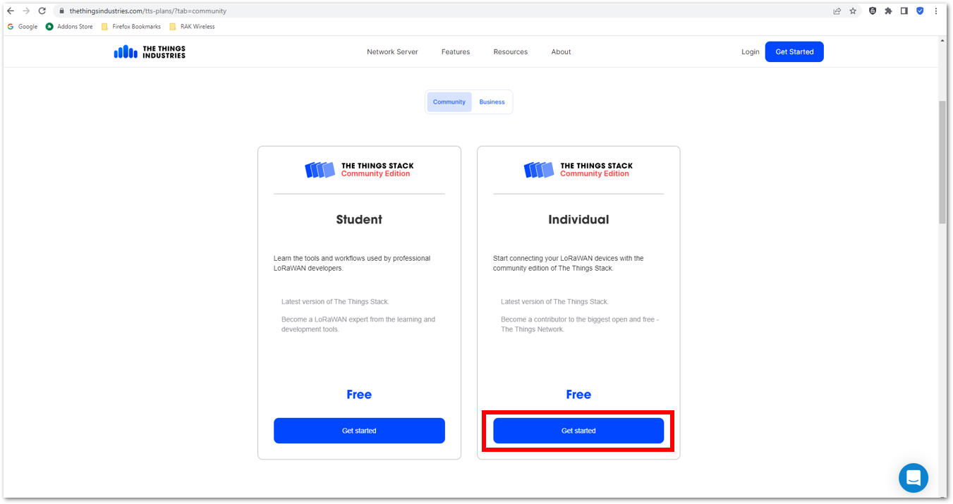 Figure 1: TTN community type
c. Sign up through The Things ID by clicking Sign up for free.
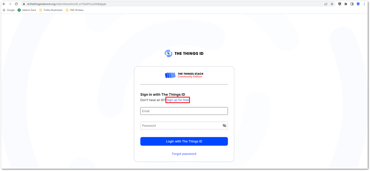 Figure 1: Sign up through The Things ID
d. Enter your details, agree to the Terms and Conditions, and click Sign up to The Things ID.
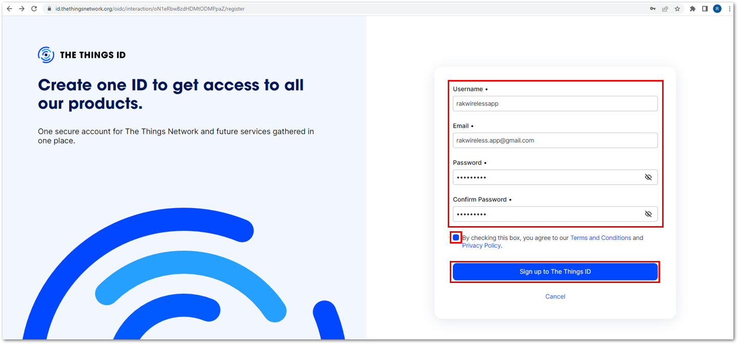 Figure 1: Enter account details
e. Then, select a cluster as shown in Figure 27.
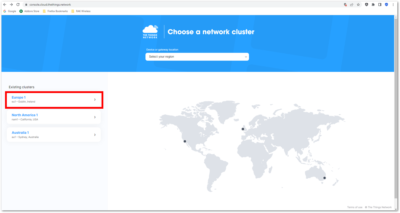 Figure 1: Select a cluster in TTN
Use the same login credentials on the TTN V2 if you have one. If you have no account yet, create one.
- Once logged in to the platform, create an application by clicking Create an application.
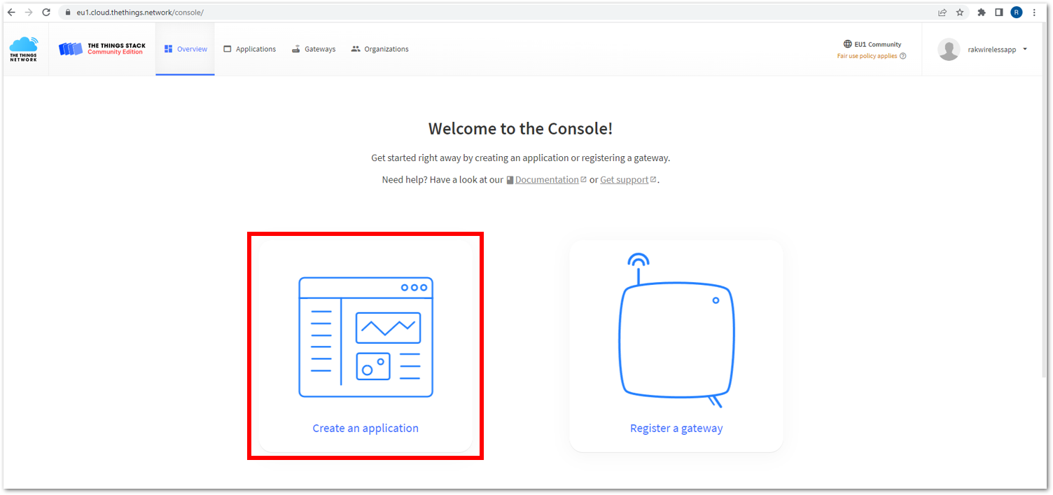 Figure 1: Create a TTN application for your LoRaWAN devices
- Navigate to the Applications tab.
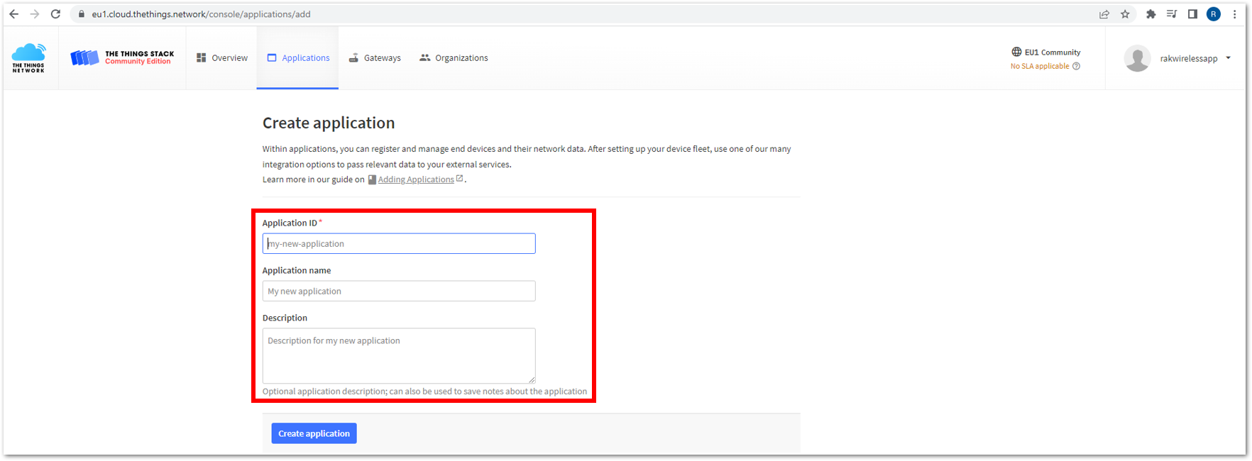 Figure 1: Details of the TTN application
- Fill in the necessary information about your application, then click Create application.
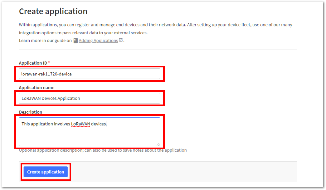 Figure 1: TTN application
If you had no errors in the previous step, the application console page should now be visible. The next step is to add end-devices to your TTN application.
LoRaWAN specifications enforce that each end-device has to be personalized and activated. There are two options for registering devices, depending on the activation mode selected. Activation can be done either via Over-The-Air-Activation (OTAA) or Activation-By-Personalization (ABP).
TTN OTAA Device Registration
- Go to your application console to register a device. To start adding an OTAA end-device, click +Register end device, as shown in Figure 31.
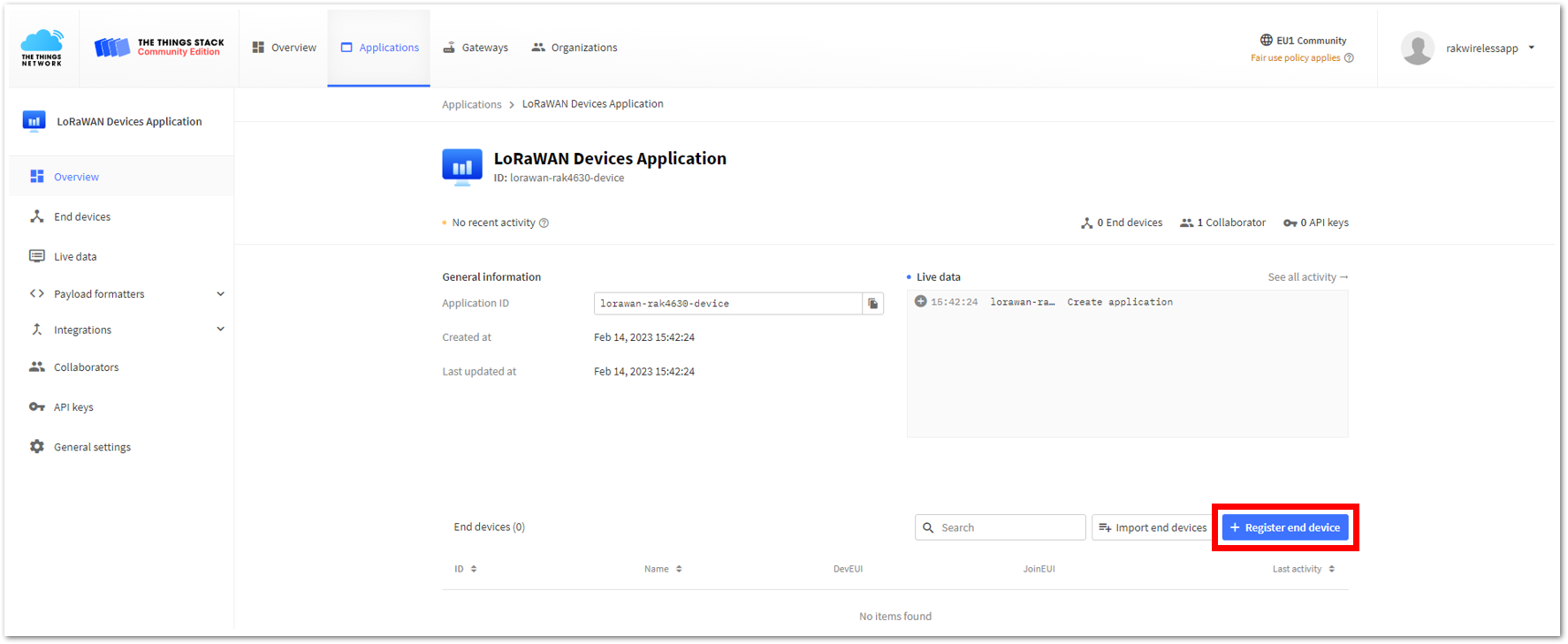 Figure 1: Register OTAA end-device
- Register the board by selecting Enter end device specifics manually.
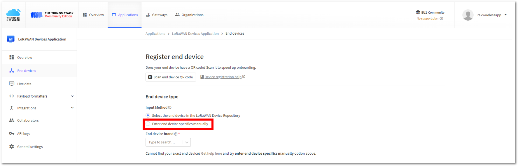 Figure 1: Enter OTAA end-device specifics manually
- Configure the Frequency plan, compatible LoRaWAN version, and supported Regional Parameters version.
 Figure 1: OTAA Frequency plan setup
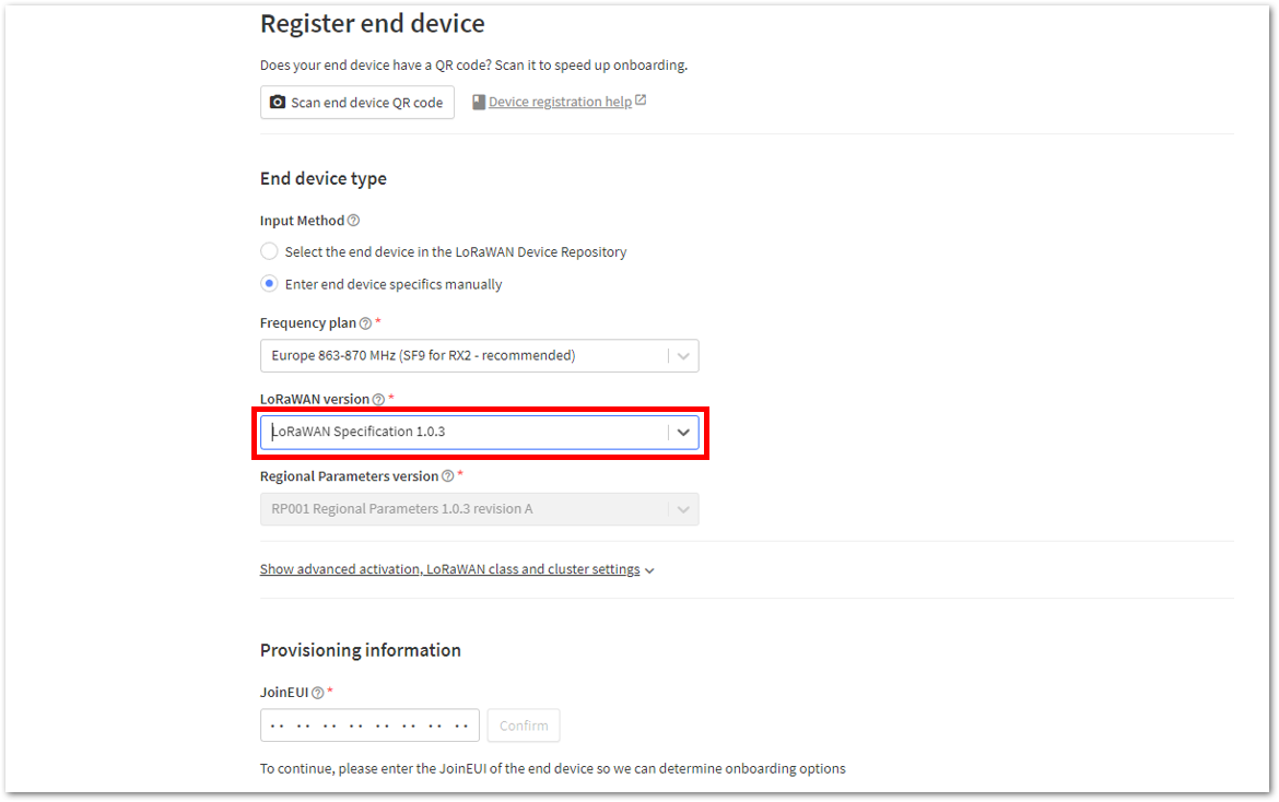 Figure 1: OTAA LoRaWAN version setup
- Set the JoinEUI by entering zeros into the field.
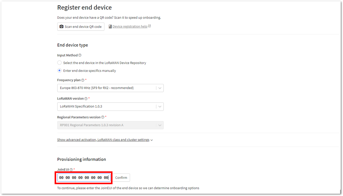 Figure 1: OTAA JoinEUI setup
- Click Show advanced activation, LoRaWAN class and cluster settings.
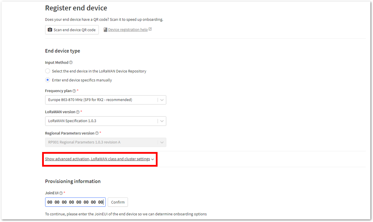 Figure 1: OTAA Show advanced activation
- Configure the following, then click Confirm.
- Activation mode: Over the air activation (OTAA)
- Additional LoRaWAN class capabilities: None (class A only)
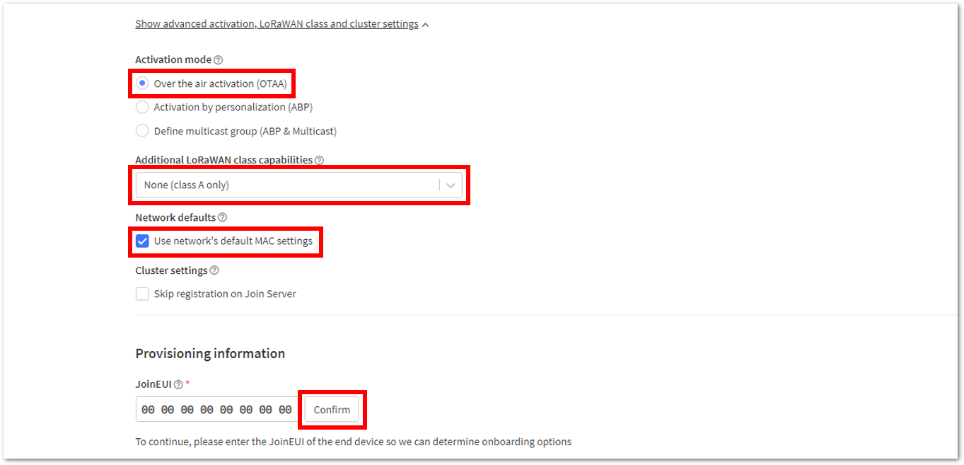 Figure 1: OTAA LoRaWAN class and cluster settings
- Once completed, enter the device's DevEUI credential in the DevEUI field. This will automatically generate the specific end-device ID of your board.
- The AppEUI, DevEUI, and AppKey are hidden in this section as these are unique to a specific device. The DevEUI is specific to every RAK11160 device, while the AppEUI and AppKey should be generated individually for each device and application.
- The AppEUI is the same as JoinEUI.
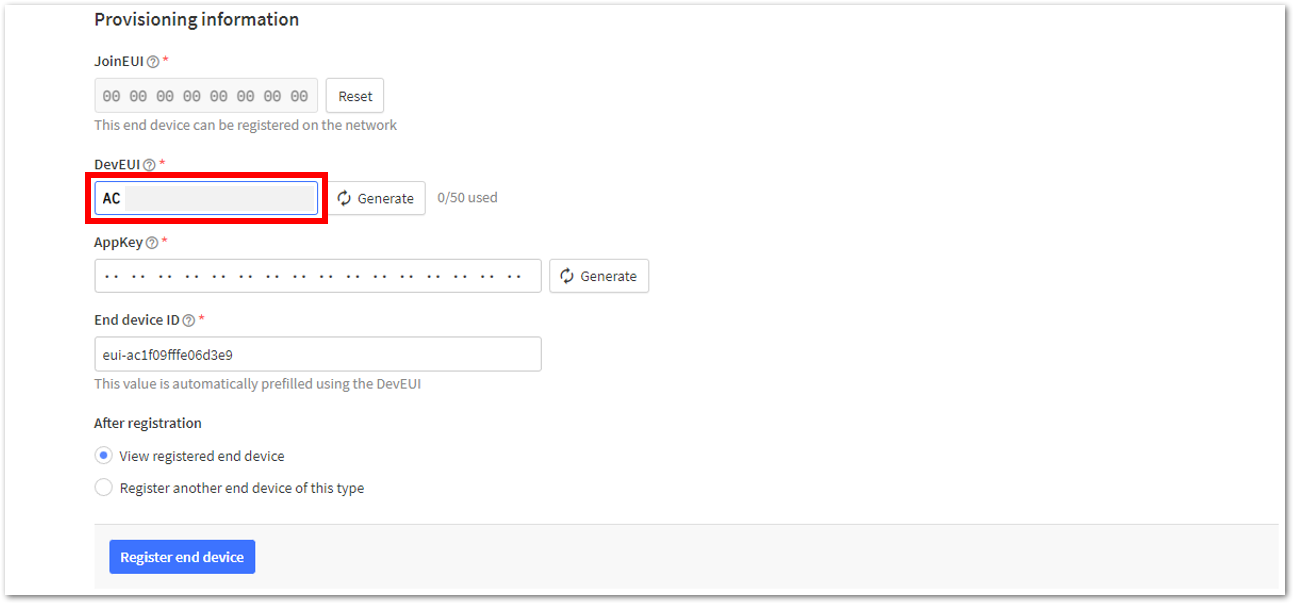 Figure 1: OTAA DevEUI credential
- Click Generate under AppKey, as shown in Figure 39.
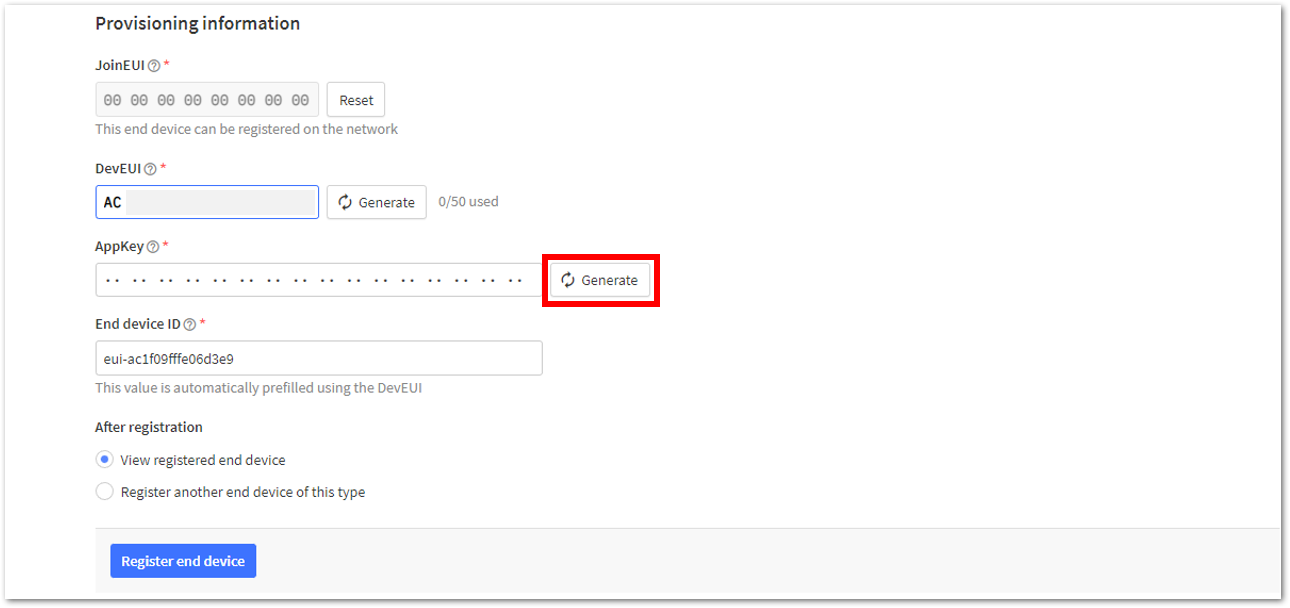 Figure 1: OTAA AppKey credential
- Once done, click Register end device to complete the process.
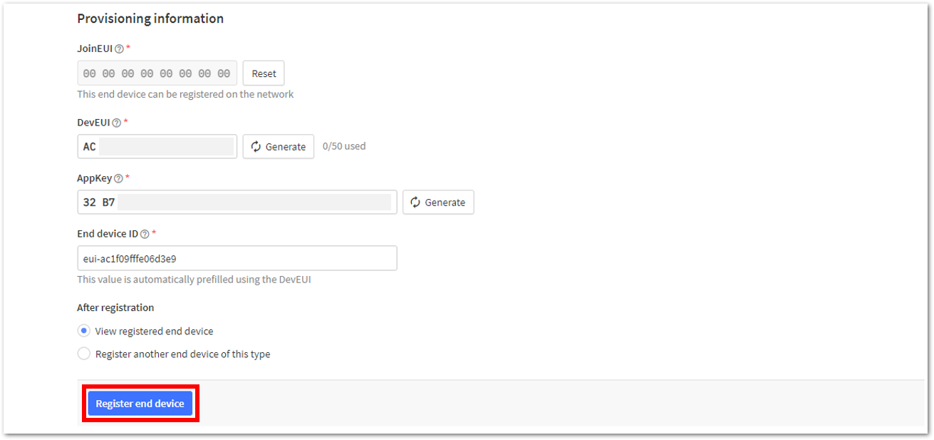 Figure 1: Click Register end device
After completing the device registration, the device should appear on the TTN console, as shown in Figure 41.
- The AppEUI, DevEUI, and AppKey are the parameters required to activate your LoRaWAN end-device via OTAA. For security reasons, the AppKey is hidden by default but can be revealed by clicking the Show button. The parameters can also be quickly copied using the Copy button.
- The three OTAA parameters on the TTN device console are MSB by default.
- These parameters are always accessible on the device console page, as shown in Figure 41.
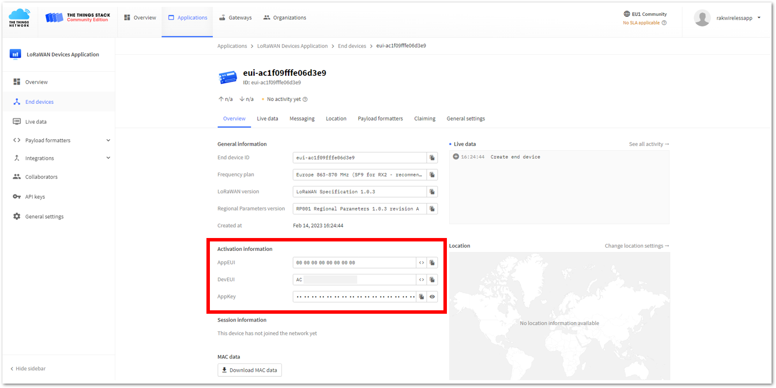 Figure 1: OTAA end-device successfully registered to TTN
Upload OTAA LoRaWAN Example to RAK11160
After successfully registering the RAK11160 device to the LoRaWAN Network Server, proceed with running the LoRaWAN OTAA demo application example.
If you use RAK11160 as a LoRaWAN modem with AT commands instead of a stand-alone device, there is a dedicated section for the OTAA AT Commands guide in the later portion of this document.
- Open the example code under RAK WisBlock RUI examples.
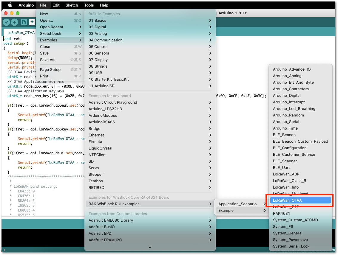 Figure 1: OTAA LoRaWAN application example
- In the example code, modify the device EUI (DevEUI) and application key (AppKey).
- The DevEUI must match the one registered on your network server. This is the same DevEUI in the RAK11160 sticker if this is the one you used in Step 7 of the TTN OTAA Device Registration section. DevEUI is MSB.
  // OTAA Device EUI MSB
  uint8_t node_device_eui[8] = {0xAC, 0x1F, 0x09, 0xFF, 0xFE, 0x03, 0xEF, 0xAB};
- Another important parameter to update is the AppKey, which must match the one configured on your network server in Step 8 of the TTN OTAA Device Registration. AppKey is an MSB.
// OTAA Application Key MSB
  uint8_t node_app_key[16] = {0xD9, 0xB8, 0x70, 0x18, 0x3E, 0xF1, 0x00, 0x1D, 0x1B, 0x4F, 0x2B, 0x4C, 0xBF, 0x60, 0xCA, 0x83};
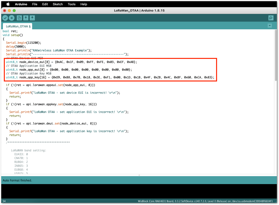 Figure 1: Update the OTAA, DevEUI, and AppKey
- This guide uses the EU868 regional band, so no changes are needed in the example code. For a different region, update the band in the code accordingly.
RAK11160 supports the following regions:
- RAK_REGION_EU433 = 0
- RAK_REGION_CN470 = 1
- RAK_REGION_RU864 = 2
- RAK_REGION_IN865 = 3
- RAK_REGION_EU868 = 4
- RAK_REGION_US915 = 5
- RAK_REGION_AU915 = 6
- RAK_REGION_KR920 = 7
- RAK_REGION_AS923-1 = 8
- RAK_REGION_AS923-2 = 9
- RAK_REGION_AS923-3 = 10
Additionally, for US915, configuring the channel mask is necessary, with channels 8 to 15 being the most commonly used in this band.
This is the additional code on how to do it:
  if(!(ret = api.lorawan.band.set(5)))      // configure to US915
  {
       Serial.printf("LoRaWan OTAA - set band is incorrect! \r\n");
       return;
  }

  uint16_t maskBuff = 0x0002;               // configure the mask for channels 8-15
  api.lorawan.mask.set(&maskBuff);
- The last step is to upload the code by clicking the Upload icon. Take note that you should select the right board and port.
- The RAK11160 should automatically enter BOOT mode when firmware is uploaded via Arduino IDE.
- If BOOT mode is not initiated, send
AT+BOOTmanually to force BOOT mode.
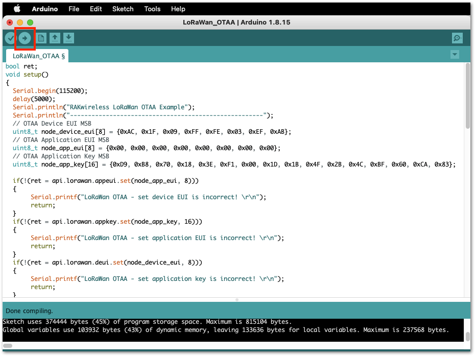 Figure 1: Upload the OTAA example code
The terminal logs should now be visible in the Serial Monitor of the Arduino IDE. If the COM port disconnects, the terminal output may not appear immediately. Reconnecting the module or pressing the reset button can help restore the output.
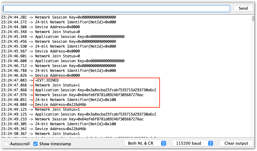 Figure 1: Terminal logs
- Check the Live data section on the LoRaWAN network server to see if the device has successfully joined with the
join requestandjoin acceptlogs.
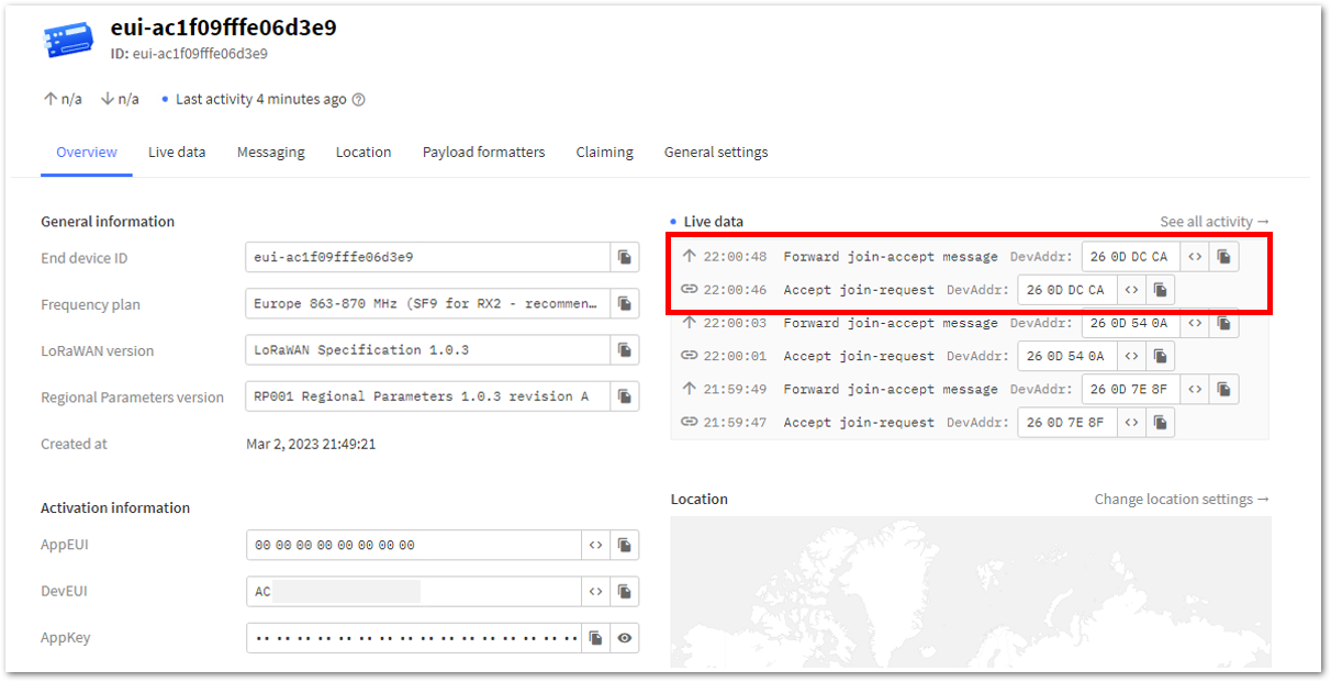 Figure 1: OTAA live data on TTN
TTN ABP Device Registration
- To register an ABP device, go to your application console and select the application to which you want your device to be added. Then click +Register end device, as shown in Figure 47.
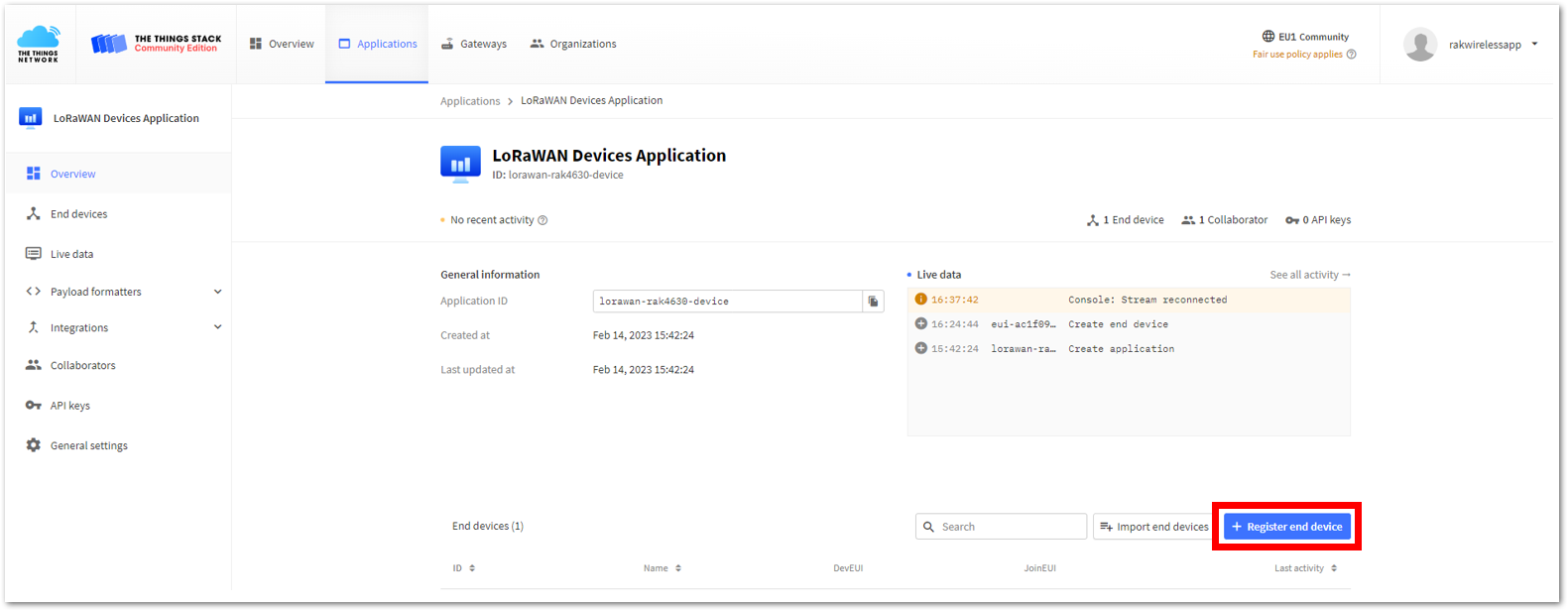 Figure 1: Register ABP end-device
- Register the board by selecting Enter end device specifics manually.
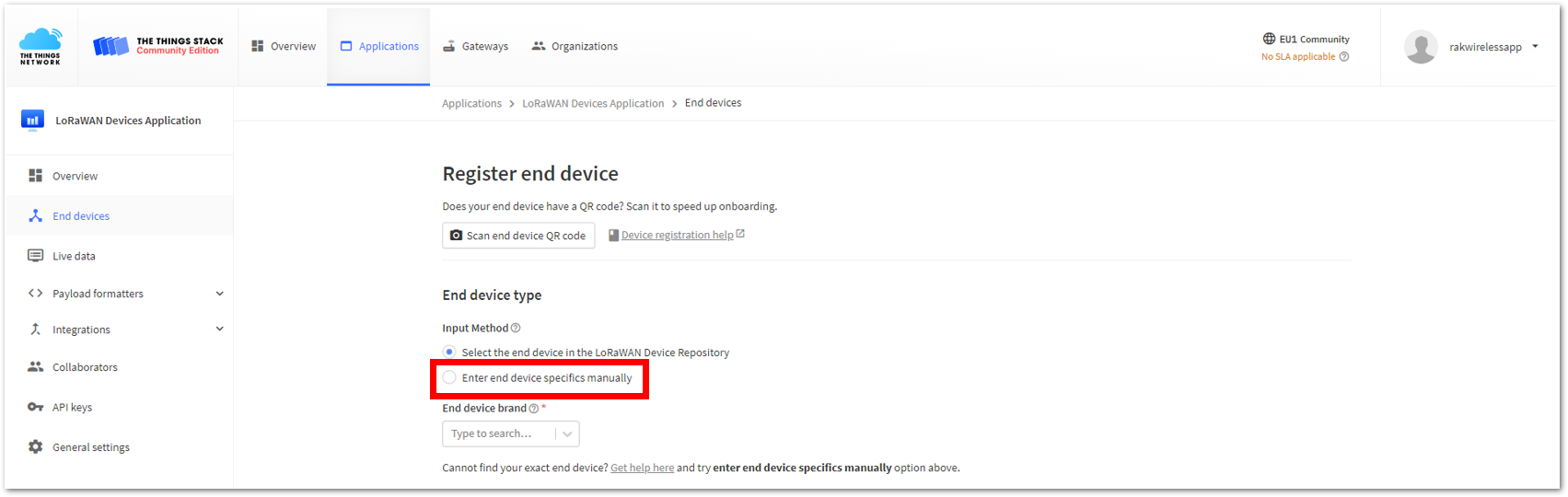 Figure 1: Enter ABP end-device specifics manually
- Configure the Frequency plan, compatible LoRaWAN version, and supported Regional Parameters version.
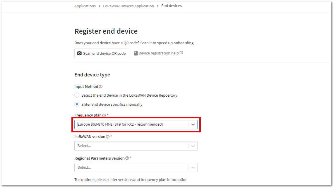 Figure 1: ABP Frequency plan setup
 Figure 1: ABP LoRaWAN version setup
- Click Show advanced activation, LoRaWAN class and cluster settings.
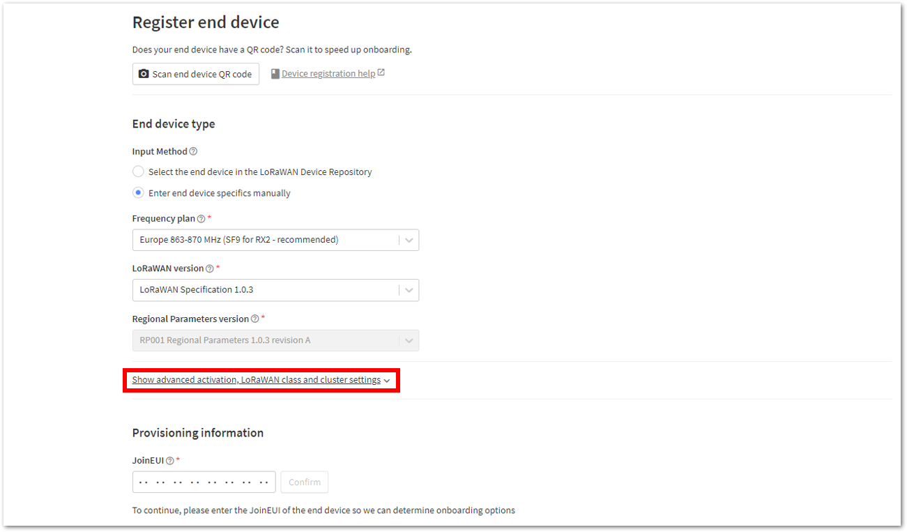 Figure 1: ABP Show advanced activation
- Configure the following, then click Confirm.
- Activation mode: Activation by personalization (ABP)
- Additional LoRaWAN class capabilities: None (class A only)
- Network defaults (tick off the box): Use network's default MAC settings
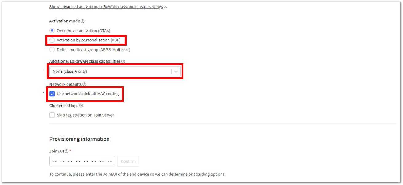 Figure 1: ABP LoRaWAN class and cluster settings
- Once completed, enter the device's DevEUI credentials in the DevEUI field. Alternatively, use the Generate button to create create a DevEUI automatically.
- The DevEUI, Device address, AppKey, and NwkSKey are hidden in this section as they are unique to each device. The DevEUI is specific to every RAK11160 device, while the Device address, AppKey, and NwkSKey should be generated individually for each device and application.
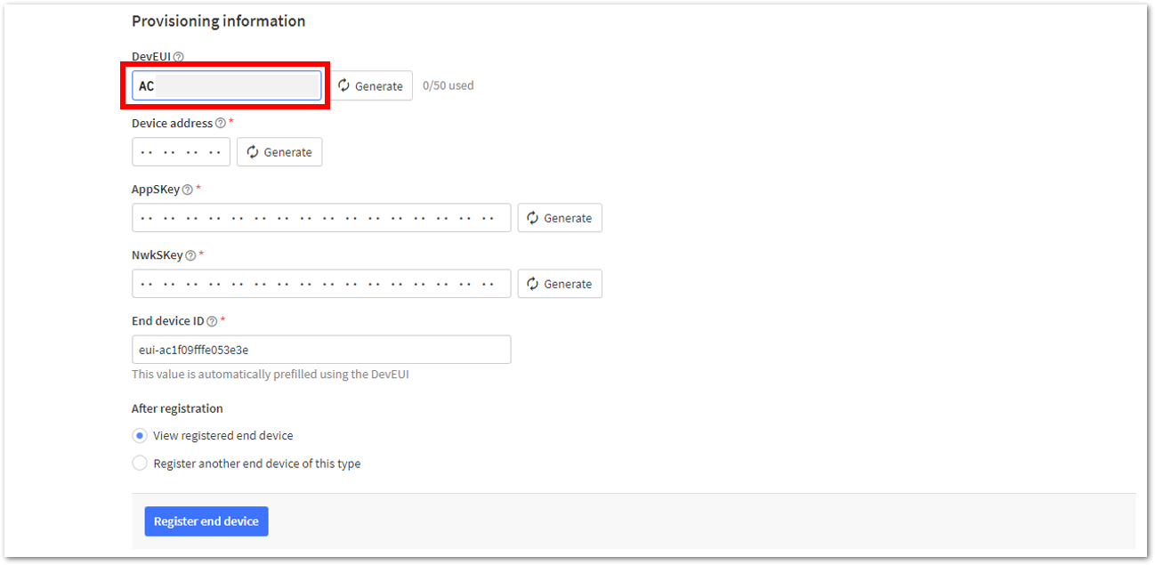 Figure 1: ABP DevEUI credential
- Click Generate under Device address, AppSKey, and NwkSKey, as shown in Figure 54 to Figure 56 respectively.
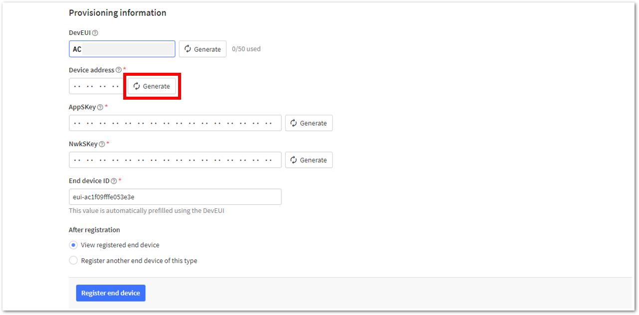 Figure 1: ABP Device address
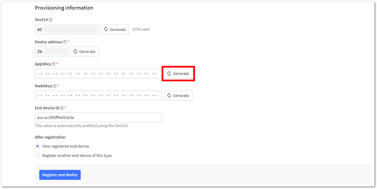 Figure 1: ABP AppSKey credential
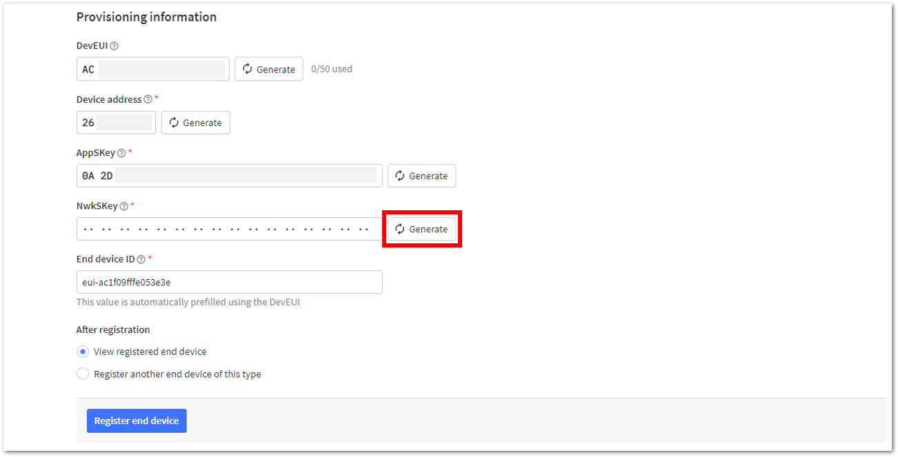 Figure 1: ABP NwkSKey credential
- Once done, click Register end device to complete the process.
 Figure 1: Click Register end device
After completing the device registration, the device should appear on the TTN console, as shown in Figure 58.
 Figure 1: ABP end-device successfully registered to TTN
Upload ABP LoRaWAN Example to RAK11160
After successfully registering the RAK11160 module to the LoRaWAN Network Server as an ABP device, proceed with running the LoRaWAN ABP demo application example.
If you use RAK11160 as a LoRaWAN modem using AT commands instead of a stand-alone device, there is a dedicated section for ABP AT Commands guide in the later portion of this document.
- Open the example code under RAK WisBlock RUI examples.
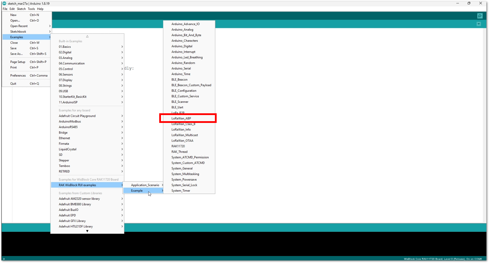 Figure 1: ABP LoRaWAN application example
- In the example code, modify the device address (DEVADDR), application session key (APPSKEY), and network session key (NWKSKEY). All these parameters should match the ones generated on the LoRaWAN network server.
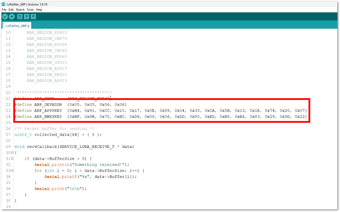 Figure 1: Update the DEVADDR, APPSKEY, and NWKSKEY
- This guide uses the EU868 regional band, so no changes are needed in the example code. For a different region, update the band in the code accordingly.
RAK11160 supports the following regions:
- RAK_REGION_EU433 = 0
- RAK_REGION_CN470 = 1
- RAK_REGION_RU864 = 2
- RAK_REGION_IN865 = 3
- RAK_REGION_EU868 = 4
- RAK_REGION_US915 = 5
- RAK_REGION_AU915 = 6
- RAK_REGION_KR920 = 7
- RAK_REGION_AS923-1 = 8
- RAK_REGION_AS923-2 = 9
- RAK_REGION_AS923-3 = 10
Additionally, for US915, configuring the channel mask is necessary, with channels 8 to 15 being the most commonly used in this band.
This is the additional code on how to do it.
  if(!(ret = api.lorawan.band.set(5)))      // configure to US915
  {
       Serial.printf("LoRaWan OTAA - set band is incorrect! \r\n");
       return;
  }

  uint16_t maskBuff = 0x0002;               // configure the mask for channels 8-15
  api.lorawan.mask.set(&maskBuff);
- The last step is to upload the code by clicking the Upload icon. Note that you should select the right board and port, as shown in the previous example LED Blinking.
- The RAK11160 should automatically enter BOOT mode when firmware is uploaded via Arduino IDE.
- If BOOT mode is not initiated, send
AT+BOOTmanually to force BOOT mode.
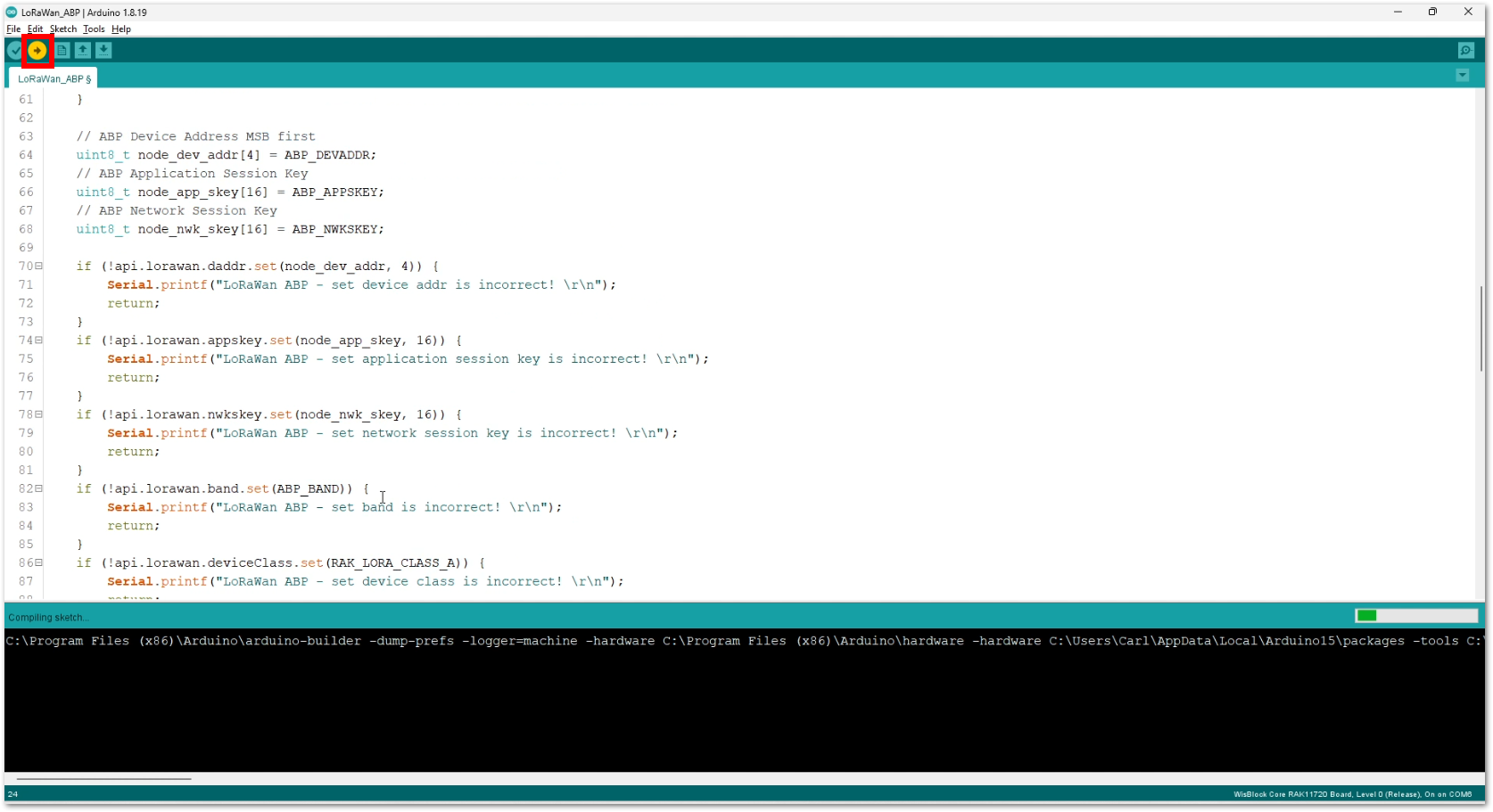 Figure 1: Upload the ABP example code
The terminal logs should now be visible in the Serial Monitor of the Arduino IDE. If the COM port disconnects, the terminal output may not appear immediately. Reconnecting the module or pressing the reset button can help restore the output.
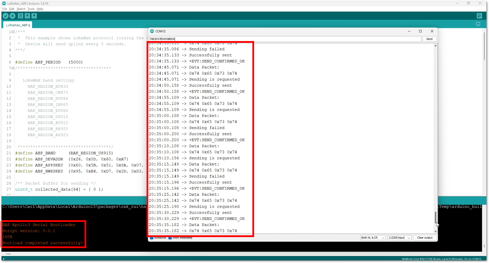 Figure 1: Terminal logs
- Check the Live data section on the LoRaWAN network server if your device is able to send uplink packets.
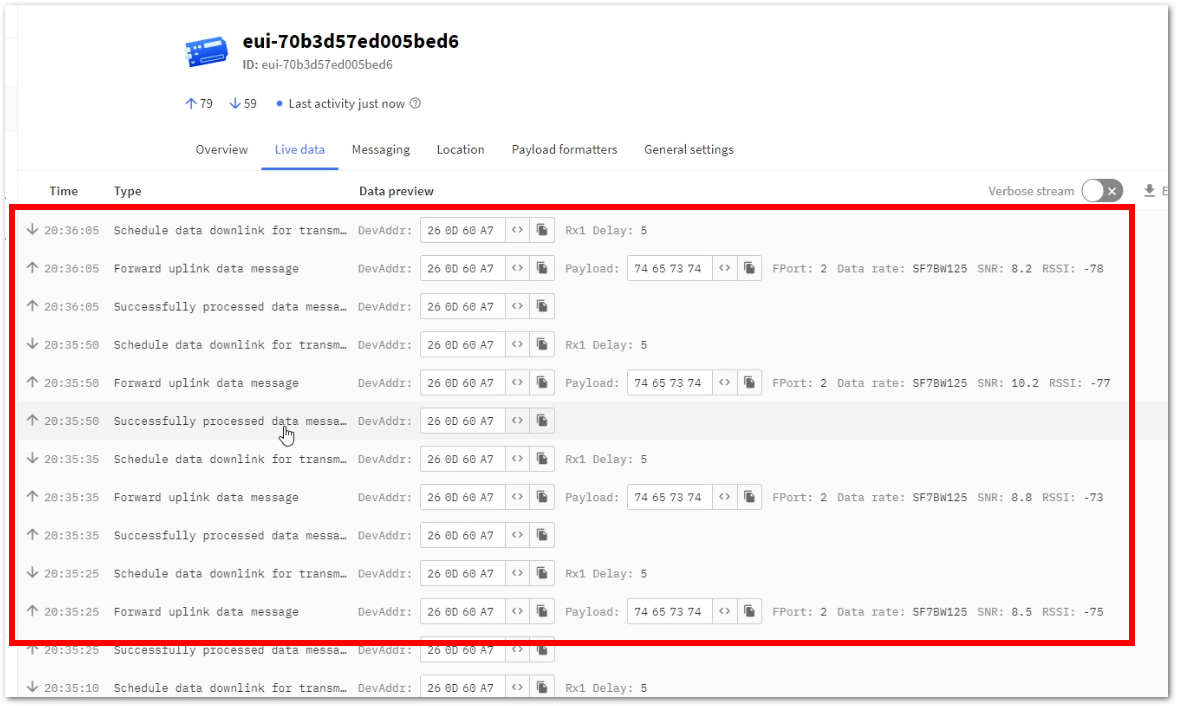 Figure 1: ABP live data on TTN
- On ABP, frame counters for both uplink and downlink need to be tracked by the device firmware. However, on RUI3 ABP, there is no tracking, and frame counts will go back to zero when the device resets. This will result in failures on uplinks and downlinks. To prevent this issue, enable the Resets frame counters option by following these steps:
a. On The Things Network (TTN) Console and go to General settings.
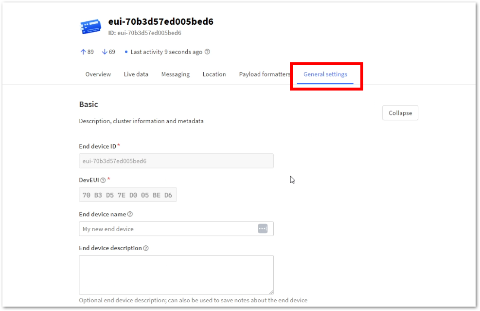 Figure 1: ABP General settings
b. Expand the Network Layer by clicking the Expand button.
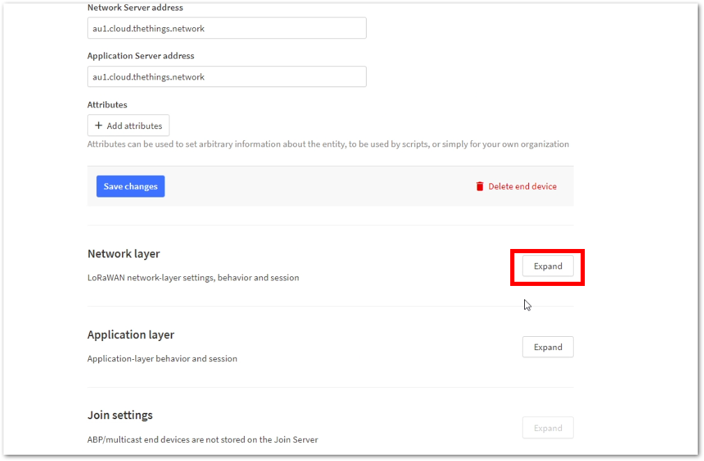 Figure 1: ABP network layer expansion
c. Click on the Advanced MAC settings dropdown.
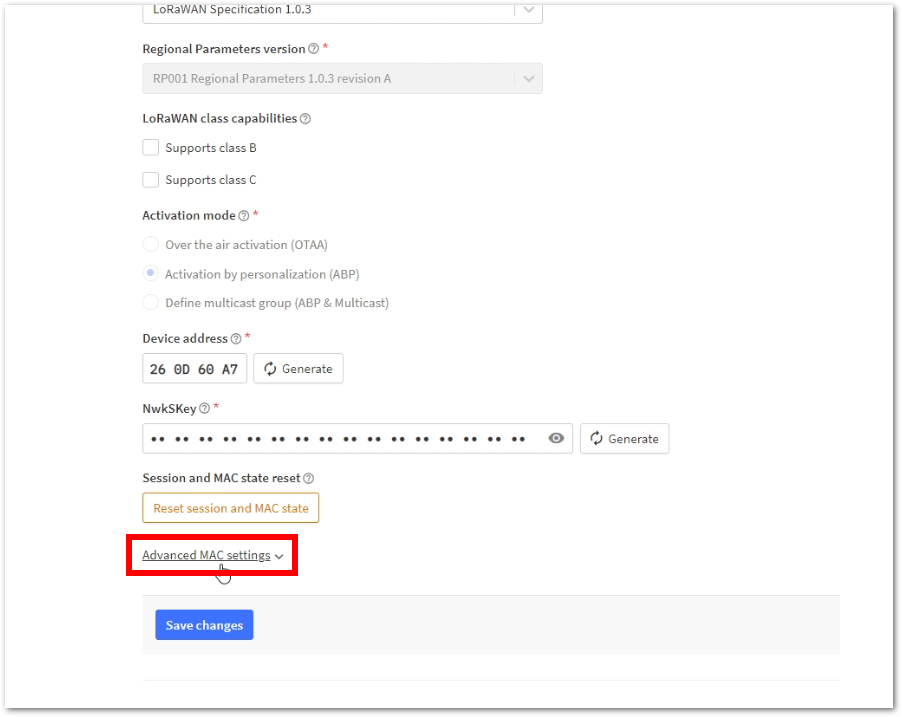 Figure 1: Advance MAC settings
d. Check Resets frame counters. With this enabled, all uplinks and downlinks will be successful even if the device resets/restarts.
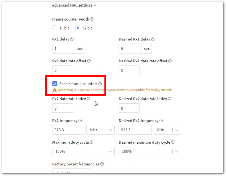 Figure 1: Resets Frame Counters
Connect with ChirpStack
This section shows how to connect the RAK11160 module to the ChirpStack platform.
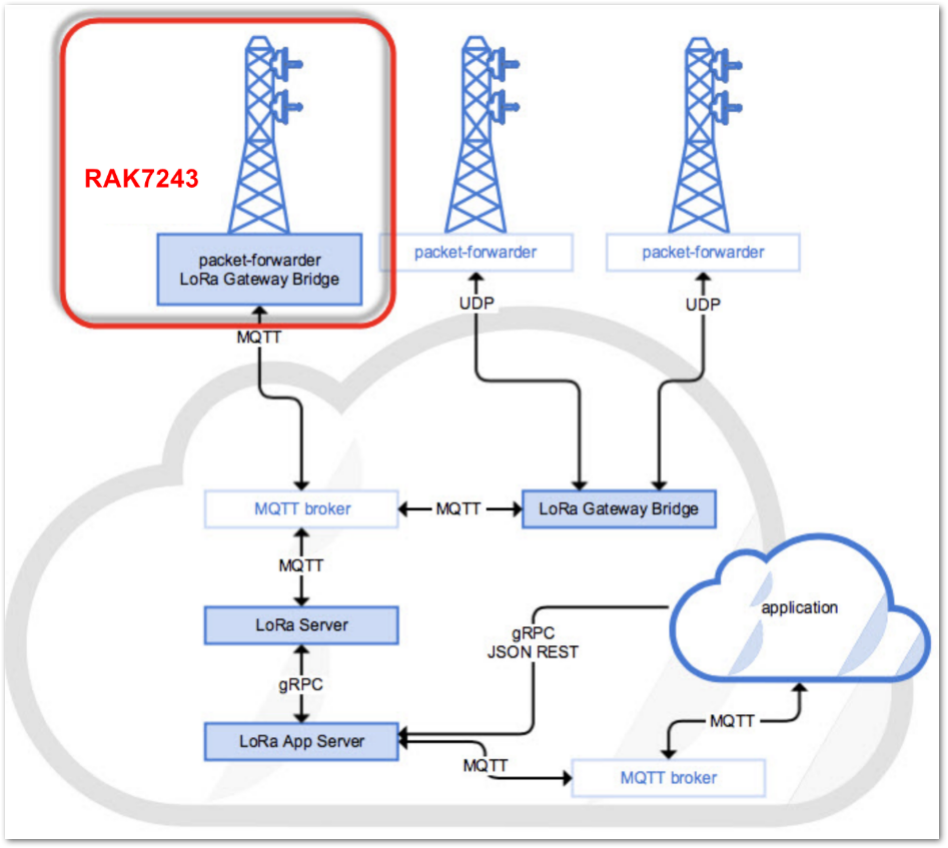 Figure 1: Connect RAK11160 to the ChirpStack platform
The ChirpStack, previously known as the LoRaServer project, provides open-source components for building LoRaWAN networks. In the case of TTN, the RAK11160 module is located in the periphery and will transmit the data to the backend servers through a LoRaWAN gateway. Learn more about ChirpStack.
In this guide, it is assumed that you are using a RAK Gateway and its built-in ChirpStack. Also, the gateway with the ChirpStack must be configured successfully. The frequency band of the nodes should be consistent with the frequency band of the gateway and ChirpStack installation.
Create a New Application on ChirpStack
- Log in to the ChirpStack server using your ChirpStack credentials.
- Navigate to the Applications section and click +CREATE to create a new application.
By default, creating a new application is recommended, but existing ones can also be reused.
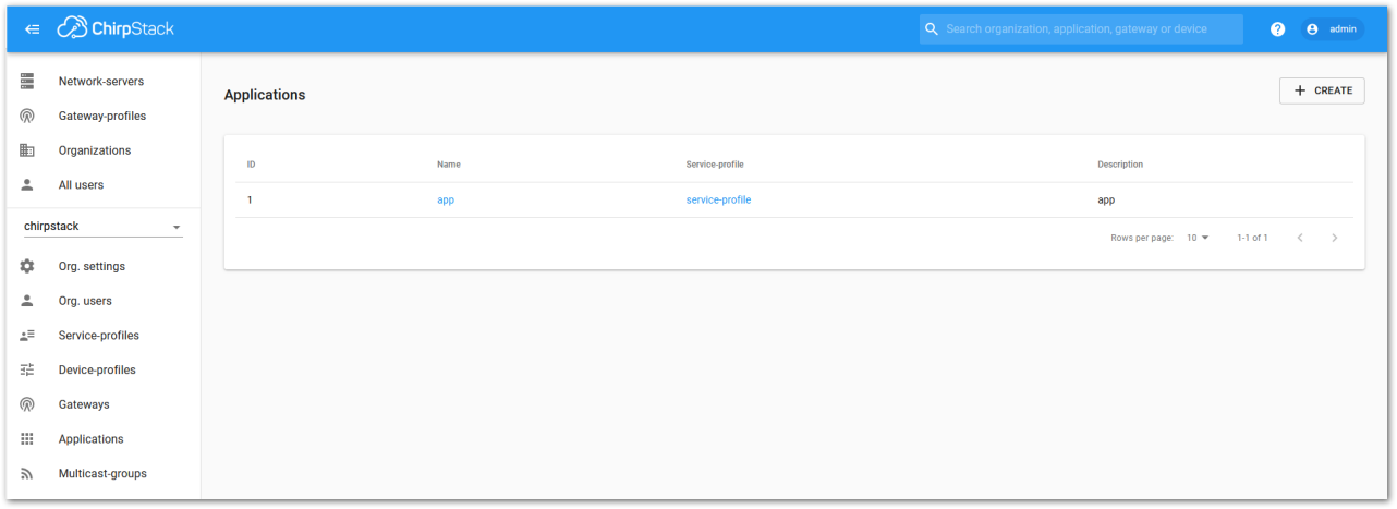 Figure 1: Applications section
Fill in the required parameters, as shown Figure 70.
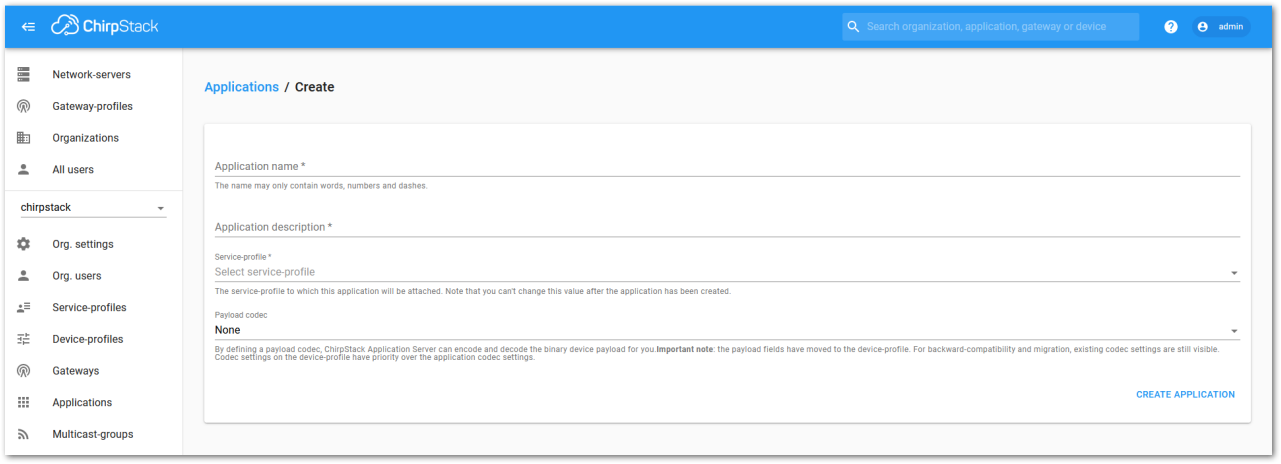 Figure 1: Create a new application
- For this setup, create an Application named rak_node_test.
ChirpStack LoraServer supports multiple system configurations, with only one by default.
- Service profile: Field is to select the system profile.
- Payload codec: It is the parsing method for selecting load data, such as parsing LPP format data.
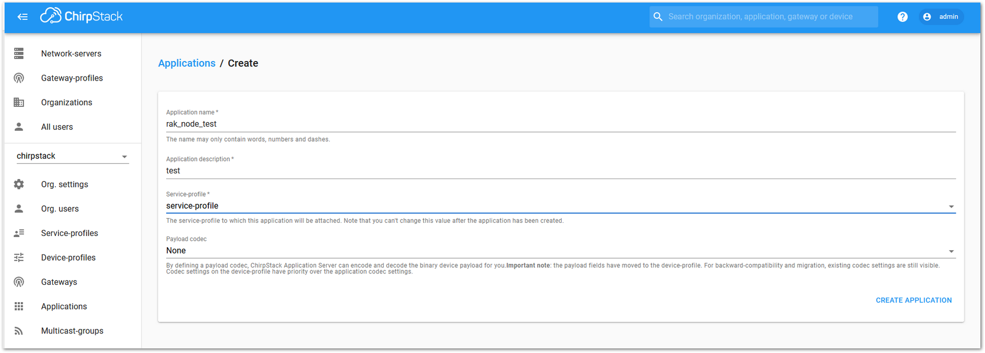 Figure 1: Fill in the parameters of an application
- Choose the application created in the previous step, then select the DEVICES tab, as shown in Figure 72 and Figure 73.
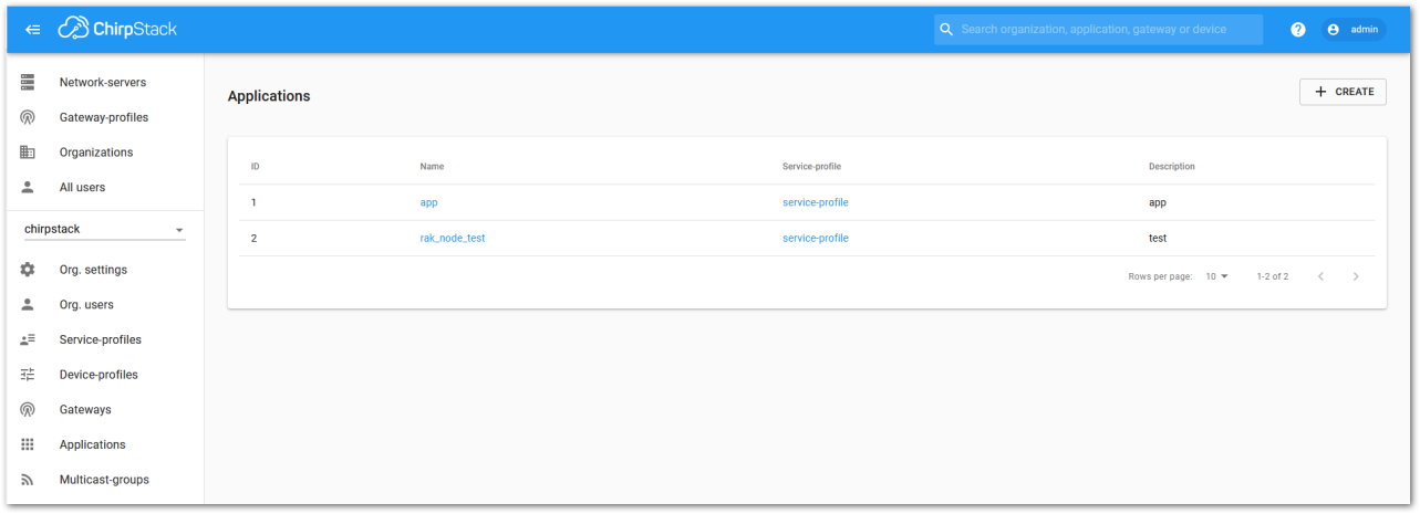 Figure 1: List of applications created
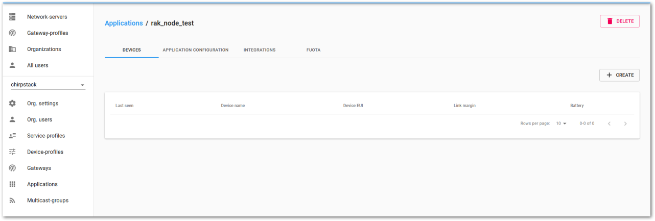 Figure 1: Application Device tab
- Once inside the DEVICE tab, create a new device (LoRaWAN node) by clicking the +CREATE button.
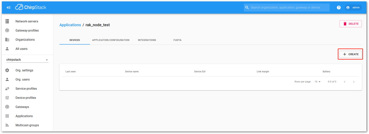 Figure 1: Add a new device
- Once the node is created, fill in the necessary data. Click the icon to automatically generate a Device EUI, or manually enter the correct Device EUI in the edit box.
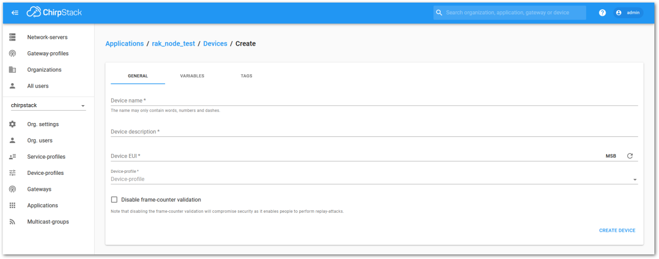 Figure 1: Add a node into the RAK11160 module
Fill in the parameters requested:
- Device name and Device description: These are descriptive texts about your device.
- Device EUI: This interface allows you to generate a Device EUI automatically by clicking the generate icon. A specific Device EUI can also be entered directly into the form.
- Device Profile:
- If you want to join in OTAA mode, select DeviceProfile_OTAA.
- If you want to join in ABP mode, select DeviceProfile_ABP.
- Device profiles DeviceProfile_OTAA and DeviceProfile_ABP are only available if you are using the built-in ChirpStack LoRaWAN Server of RAK Gateways.
- If you have your own ChirpStack installation, set up the device profile with
LoRaWAN MAC version 1.0.3andLoRaWAN Regional Parameters revision Bto make it compatible with RAK11160.
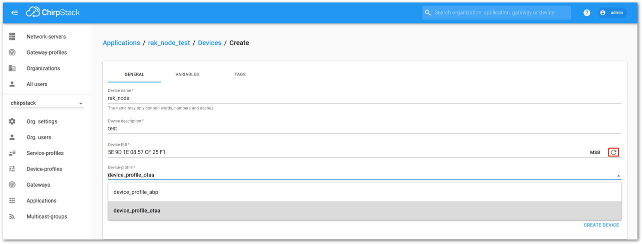 Figure 1: Generate a new device EUI
 ChirpStack OTAA Device Registration
- If you have selected DeviceProfile_OTAA, as shown in Figure 77, after the device is created, an Application Key must be created for this device.
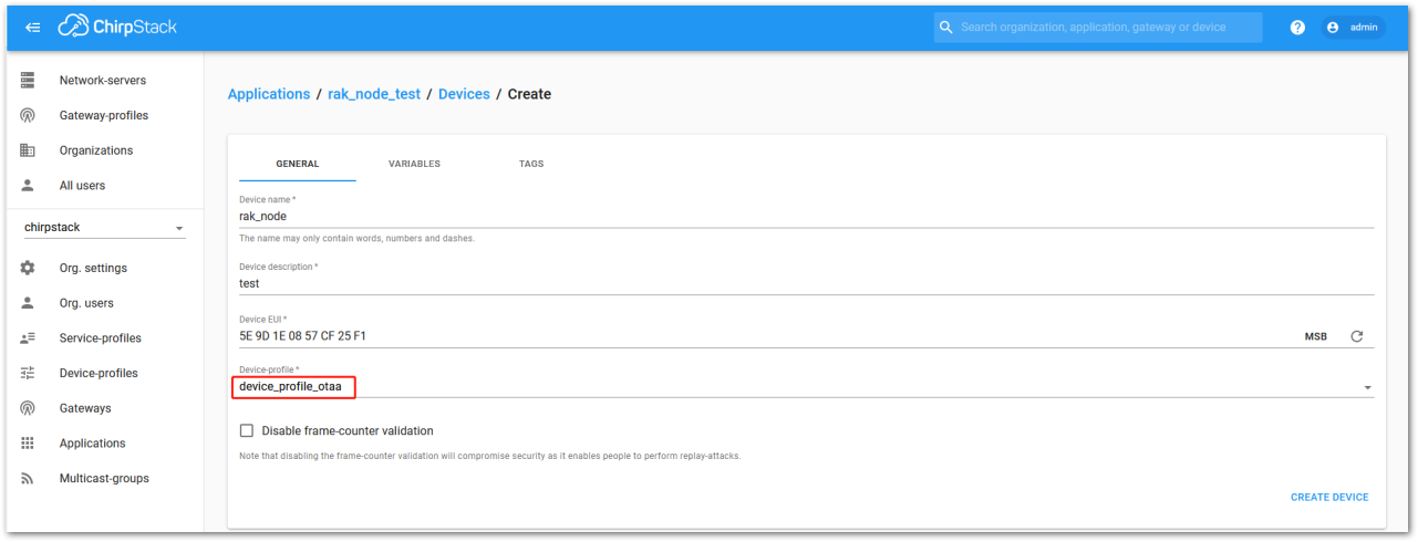 Figure 1: ChirpStack OTAA activation
- A previously created Application Key can be entered here, or a new one can be generated automatically by clicking the icon highlighted in red in Figure 78.
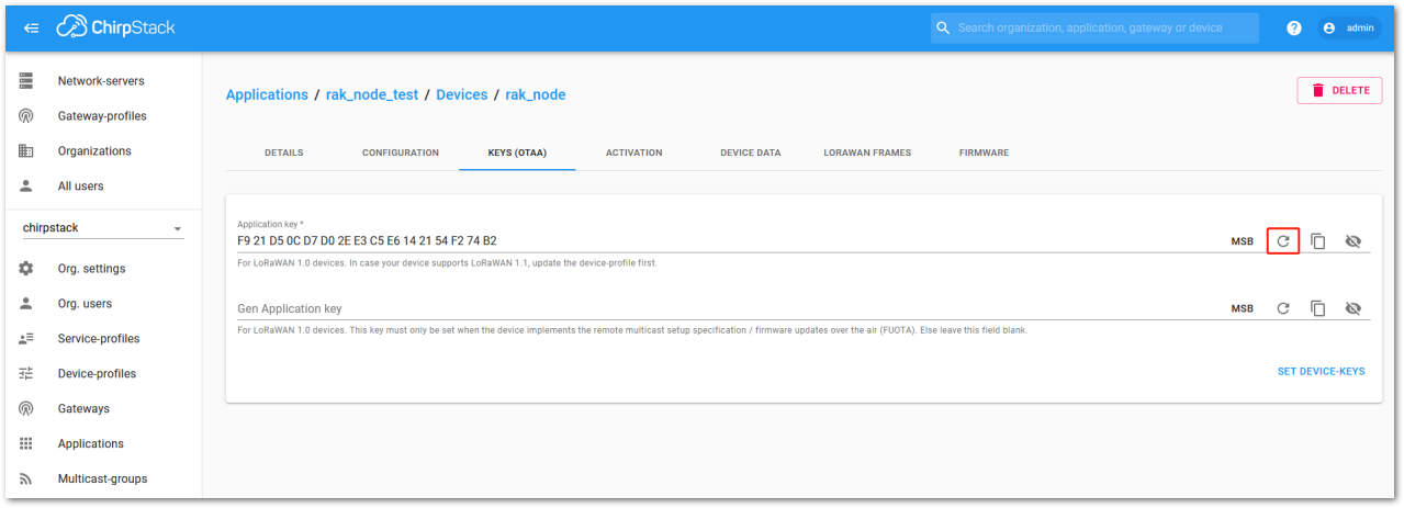 Figure 1: ChirpStack OTAA set application keys
- Once the Application Key is added to the form, the process can be finalized by clicking the SET DEVICE-KEYS button.
- As shown in Figure 79, a new device should be listed in the DEVICES tab. The most important parameters, such as the Device EUI, are shown in the summary.
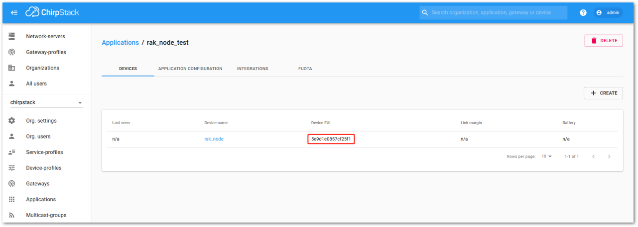 Figure 1: ChirpStack OTAA list of the device in the device tab
- To end the process, it is a good practice to review that the Application Key is properly associated with this device. The Application Key can be verified in the KEYS (OTAA) tab, as shown in Figure 80.
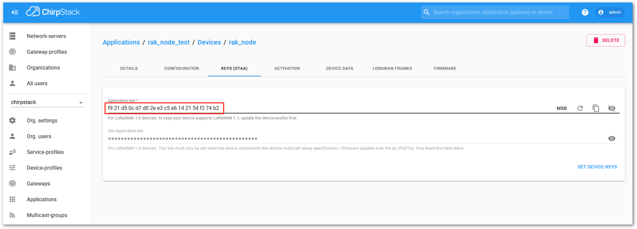 Figure 1: Application key associated with the new device
- After registering the RAK11160 in ChirpStack as an OTAA device, create a custom firmware using the Arduino IDE for the RAK11160 or use OTAA AT Commands with an external MCU host.
Standard OTAA mode requires the Device EUI, Application Key, and Application EUI, but in ChirpStack’s implementation, only the Device EUI and the Application Key are mandatory. The Application EUI is not required and is not recorded in the Application tab. However, the Device EUI can be reused as the Application EUI when configuring the node.
ChirpStack ABP Device Registration
- When registering a new device, selecting DeviceProfile_ABP, as shown in Figure 81, signals to the ChirpStack platform that the device will join the LoRaWAN network using ABP mode.
Tick Disable counting frame verification to prevent synchronization issues during testing. When the module restarts, the frame counter resets to zero, which ChirpStack may interpret as a replay attack. While disabling this feature is safe for testing, ensure it is enabled in production. Note that in RAK11160, the frame counter resets upon reboot.
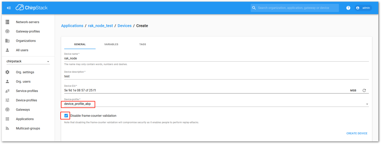 Figure 1: Configure a device in the ChirpStack console
- After selecting the ABP mode, the following parameters will appear under the ACTIVATION tab:
- Device Address
- Network Session Key
- Application Session Key
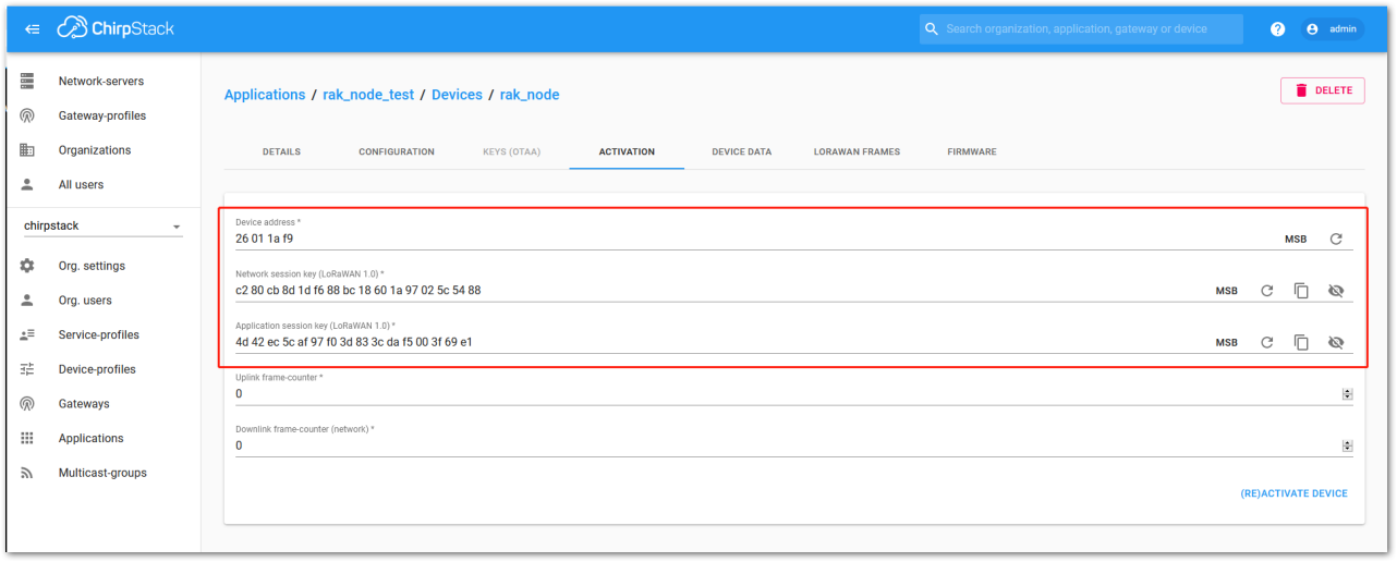 Figure 1: ChirpStack ABP activation parameters
- The parameters can be generated as random numbers by the platform or can be set with user values. Once these parameters are filled in properly, the process is completed by clicking on the ACTIVATE DEVICE button.
- After registering the RAK11160 in ChirpStack as an ABP device, create a custom firmware using Arduino IDE for RAK11160 or use ABP AT Commands with external MCU host.
Wi-Fi Example with RUI3 API
The RUI3 BSP does not include an example for the usage of Wi-Fi on the RAK11160. This simple example code shows how to connect to an Wi-Fi AP in station mode.
For easier understanding, the code is split here into several parts.
- Testing the connection to ESP8684 by powering up the ESP8684 and check the response received.
The ESP8684 can be forced into low power mode by controlling the PA0 GPIO of the STM32WLE5. If set to low, the ESP8684 is shut down, if set to high, the ESP8684 is powering up.
Connection to the ESP8684 is done by sending an
ATto it through Serial1 of the STM32WLE5 and wait for the response, which should includeOK.
Expected response is
AT

OK
Click to view the example code.
	// Initialize interface to ESP8684
	Serial1.begin(115200);
	// Enable ESP8684
	pinMode(WB_ESP8684, OUTPUT);
	digitalWrite(WB_ESP8684, HIGH);
	// Wait for ESP8684 bootup
	bool found_esp8684 = false;
	time_t start = millis();
	while ((millis() - start) < 30000)
	{
		Serial1.println("AT");
		Serial1.flush();
		if (wait_ok_response(10000))
		{
			Serial.println("ESP8684 found");
			found_esp8684 = true;
			break;
		}
		delay(500);
	}
- Set the ESP8684 into Wi-Fi station mode to be able to connect to a Wi-Fi AP.
Expected response is
AT+CWMODE=1,1

OK
Click to view the example code.
	// Set ESP8684 into station mode and enable auto connect AT+CWMODE=1,1
	// Clear send buffer
	memset(wrx_buf, 0, 512);
	snprintf(wrx_buf, 511, "AT+CWMODE=1,1\r\n");
	Serial1.printf("%s", wrx_buf);
	Serial1.flush();
	if (wait_ok_response(10000))
	{
		Serial.printf("\r\nESP8684 mode set: ==>%s<==\r\n", wtx_buf);
	}
	else
	{
		Serial.printf("\r\nESP8684 mode failed: ==>%s<==\r\n", wtx_buf);
	}
- Request connection to the selected Wi-Fi AP
Expected response is
AT+cwjap="<MQTT_WIFI_APN>","<MQTT_WIFI_PW>"
WIFI DISCONNECT
WIFI CONNECTED
WIFI GOT IP

OK
Click to view the example code.
	// Connect ESP8684 to Wi-Fi AP
	// Clear send buffer
	memset(wrx_buf, 0, 512);
	snprintf(wrx_buf, 511, "AT+CWJAP=\"%s\",\"%s\"\r\n", MQTT_WIFI_APN, MQTT_WIFI_PW);
	Serial1.printf("%s", wrx_buf);
	Serial1.flush();
	/** Expected response ********************
	AT+cwjap="<MQTT_WIFI_APN>","<MQTT_WIFI_PW>"
	WIFI DISCONNECT
	WIFI CONNECTED
	WIFI GOT IP

	OK
	*****************************************/
	if (wait_ok_response(10000))
	{
		Serial.printf("\r\nESP8684 connected: ==>%s<==\r\n", wtx_buf);
	}
	else
	{
		Serial.printf("\r\nESP8684 not connected: ==>%s<==\r\n", wtx_buf);
	}
Here is the complete example code:
Click to view the example code.
#include <Arduino.h>

// Define enable pin for ESP8684
#define WB_ESP8684 PA0

/** Wi-Fi TX buffer */
char wtx_buf[512];
/** Wi-Fi RX buffer */
char wrx_buf[512];

/** Wi-Fi AP name */
char MQTT_WIFI_APN[32] = "RAKwireless";
/** Wi-Fi AP password */
char MQTT_WIFI_PW[32] = "RAKwireless";

/**
 * @brief Wait for response from ESP8684
 *
 * @param timeout time to wait in milliseconds
 * @param wait_for character array to wait for
 * @return true "OK" string received
 * @return false "OK" string not received, timeout
 */
bool wait_ok_response(time_t timeout)
{
	time_t start = millis();
	int buff_idx = 0;
	bool got_ok = false;

	// Clear TX buffer
	memset(wtx_buf, 0, 512);

	while ((millis() - start) < timeout)
	{
		if (Serial1.available() != 0)
		{
			char rcvd = Serial1.read();
			wtx_buf[buff_idx] = rcvd;
			buff_idx++;
			if (buff_idx == 512)
			{
				// Buffer overflow, return false
				return false;
			}

			if (strstr(wtx_buf, "OK") != NULL)
			{
				return true;
			}
		}
		delay(5);
	}
	return false;
}

/**
 * @brief Arduino setup function, called once
 *
 */
void setup(void)
{
	// Start Serial
	Serial.begin(115200);

	// Delay for 5 seconds to give the chance for AT+BOOT
	delay(5000);

	api.system.firmwareVersion.set("RAK11160-WIFI");

	Serial.println("RAK11160 Wi-Fi");
	Serial.println("---------------------------------------------------------------");
	Serial.println("Setup the device with WisToolBox or AT commands before using it");
	Serial.println("---------------------------------------------------------------");

	// Initialize interface to ESP8684
	Serial1.begin(115200);
	// Enable ESP8684
	pinMode(WB_ESP8684, OUTPUT);
	digitalWrite(WB_ESP8684, HIGH);
	// Wait for ESP8684 bootup
	bool found_esp8684 = false;
	time_t start = millis();
	while ((millis() - start) < 30000)
	{
		Serial1.println("AT");
		Serial1.flush();
		/** Expected response ********************
		AT

		OK
		*****************************************/
		if (wait_ok_response(10000))
		{
			Serial.println("ESP8684 found");
			found_esp8684 = true;
			break;
		}
		delay(500);
	}

	// Set ESP8684 into station mode and enable auto connect AT+CWMODE=1,1
	// Clear send buffer
	memset(wrx_buf, 0, 512);
	snprintf(wrx_buf, 511, "AT+CWMODE=1,1\r\n");
	Serial1.printf("%s", wrx_buf);
	Serial1.flush();
	/** Expected response ********************
	AT+CWMODE=1,1

	OK
	*****************************************/
	if (wait_ok_response(10000))
	{
		Serial.printf("\r\nESP8684 mode set: ==>%s<==\r\n", wtx_buf);
	}
	else
	{
		Serial.printf("\r\nESP8684 mode failed: ==>%s<==\r\n", wtx_buf);
	}

	// Connect ESP8684 to Wi-Fi AP
	// Clear send buffer
	memset(wrx_buf, 0, 512);
	snprintf(wrx_buf, 511, "AT+CWJAP=\"%s\",\"%s\"\r\n", MQTT_WIFI_APN, MQTT_WIFI_PW);
	Serial1.printf("%s", wrx_buf);
	Serial1.flush();
	/** Expected response ********************
	AT+cwjap="<MQTT_WIFI_APN>","<MQTT_WIFI_PW>"
	WIFI DISCONNECT
	WIFI CONNECTED
	WIFI GOT IP

	OK
	*****************************************/
	if (wait_ok_response(10000))
	{
		Serial.printf("\r\nESP8684 connected: ==>%s<==\r\n", wtx_buf);
	}
	else
	{
		Serial.printf("\r\nESP8684 not connected: ==>%s<==\r\n", wtx_buf);
	}
}

/**
 * @brief Arduino loop. Not used
 *
 */
void loop(void)
{
	api.system.sleep.all();
}
There are many options to setup the ESP8684, only the basic commands are shown here. For a full description how to control the ESP8684, please check the Espressif AT command manual.
More examples for the RAK11160 can be found in the RUI3-Best-Practices on Github. A more functional example that uses the RAK11160 as a gateway between LoRa P2P devices and an MQTT server can be found in the RUI3-Best-Practices
RAK11160 as a LoRa/LoRaWAN Modem via AT Command
The RAK11160 module can be configured using AT commands via the UART0 interface by default (UART1 can be used as well if configured correctly). A USB-to-UART TTL adapter and a serial terminal tool are required to connect the RAK11160 to a computer's USB port. Using the WisToolBox is highly recommended for convenient AT command execution and real-time console output. The RAK11160 can be configured in two ways:
- LoRaWAN End-Device
- LoRa P2P: Point-to-point communication between two RAK11160 modules.
UART Parameters for AT Commands:
- Baud Rate: 115200 baud (Default but configurable)
- Data Bits: 8 bits
- Stop Bits: 1 stop bit
- Parity: NONE
OTAA Configuration for TTN via WisToolBox Console
The RAK11160 module can be configured using WisToolBox to do the OTAA configuration. WisToolBox is a software tool that supports RAK11160 module. It automatically detects the RAK11160 module once connected to the PC. Below are the options in WisToolBox through which the OTAA configuration can be done.
Below are the steps for setting up your RAK11160 using WisToolBox Console.
- To begin the configuration, type
ATEto enable command echoing. Then, press Enter.
It is recommended to start by testing the console and verifying that the current configuration is working by sending these two AT commands:
AT
ATE
ATE is useful for tracking the commands and troubleshooting.
You will receive OK when you input the two commands. After setting ATE, see all the commands you input together with the replies.
If there is no OK or any reply, check if the device is powered correctly. If you are getting power from a USB port, ensure that you have a good USB cable.
 Figure 1: Type a command to send
 Figure 1: Enable local echoing
 Figure 1: Local echoing enabled
- Set the LoRaWAN join mode to OTAA. To determine the required parameter, type
AT+NJM?in the console terminal and press Enter.
 Figure 1: Join mode query
 Figure 1: Join mode options
- For OTAA, input
AT+NJM=1and then press Enter as shown in Figure 88.
 Figure 1: OTAA join mode
- Once done, set the LoRaWAN region to EU868. To verify the required parameter, type
AT+BAND?in the console terminal and press Enter. For EU868, enterAT+BAND=4and press Enter. For other regional bands, refer to the List of band parameter options table below.
Set the frequency/region to EU868.
AT+BAND=4
- Based on the selected Regional Band, configuring the sub-band on the RAK11160 may be necessary to ensure compatibility with the gateway and LoRaWAN network server. This is particularly important for bands such as US915, AU915, and CN470.
- To configure the masking of channels for the sub-bands, use the
AT+MASKcommand that can be found on the AT Command Manual. - To illustrate, use sub-band 2 by sending the command
AT+MASK=0002.
| Code | Regional Band |
|---|---|
| 0 | EU433 |
| 1 | CN470 |
| 2 | RU864 |
| 3 | IN865 |
| 4 | EU868 |
| 5 | US915 |
| 6 | AU915 |
| 7 | KR920 |
| 8 | AS923-1 |
| 9 | AS923-2 |
| 10 | AS923-3 |
| 11 | AS923-4 |
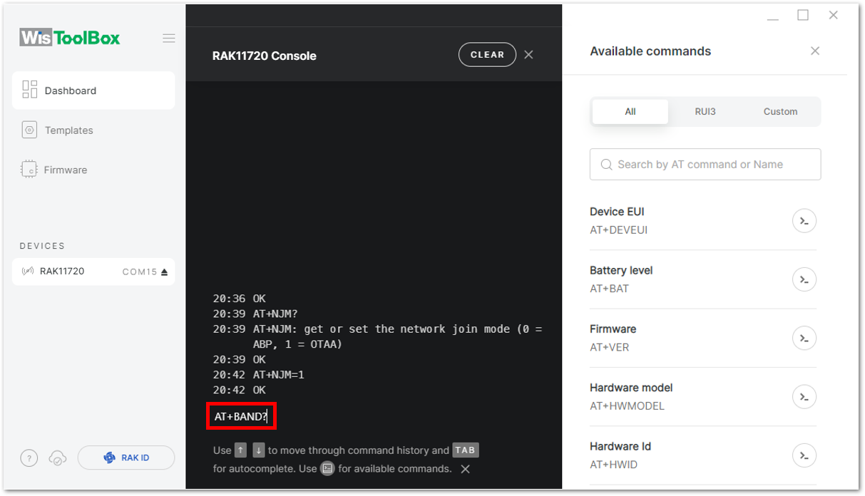 Figure 1: Frequency band query
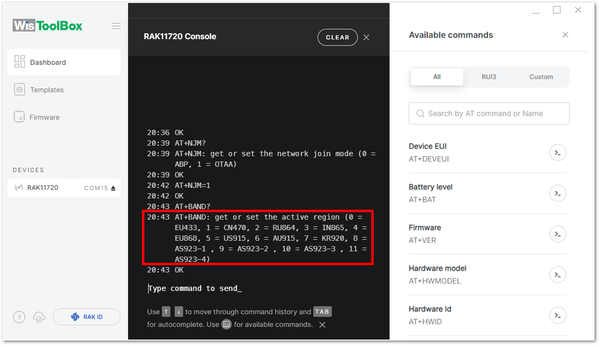 Figure 1: Frequency band options
- For EU868, enter
AT+BAND=4and press Enter. For other regional bands, refer to the List of band parameter options table below.
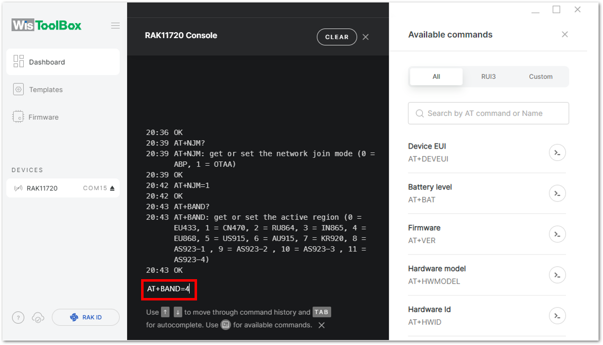 Figure 1: EU868 frequency band
- Update the OTAA credentials of the device. Open the console where the RAK11160 end device was created, copy the specific Activation information needed.
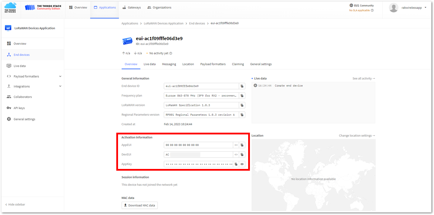 Figure 1: Your created OTAA device overview in the TTN Console
a. Copy the AppEUI credential, as shown in Figure 93.
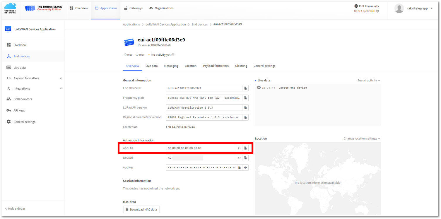 Figure 1: Copy the AppEUI credential from TTN
b. Go to the WisToolBox console and write the appropriate AT command.
- For the AppEUI, write the
AT+APPEUIcommand, as shown in Figure 94 to Figure 96.
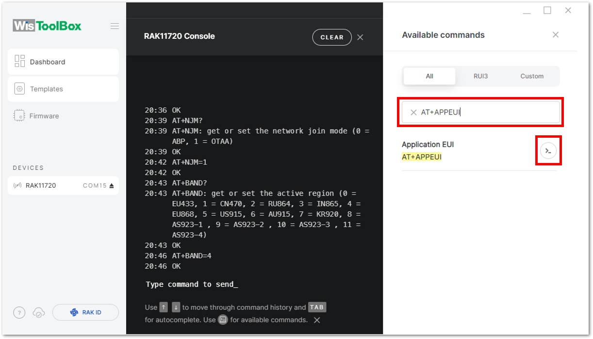 Figure 1: Search for the AppSKey command
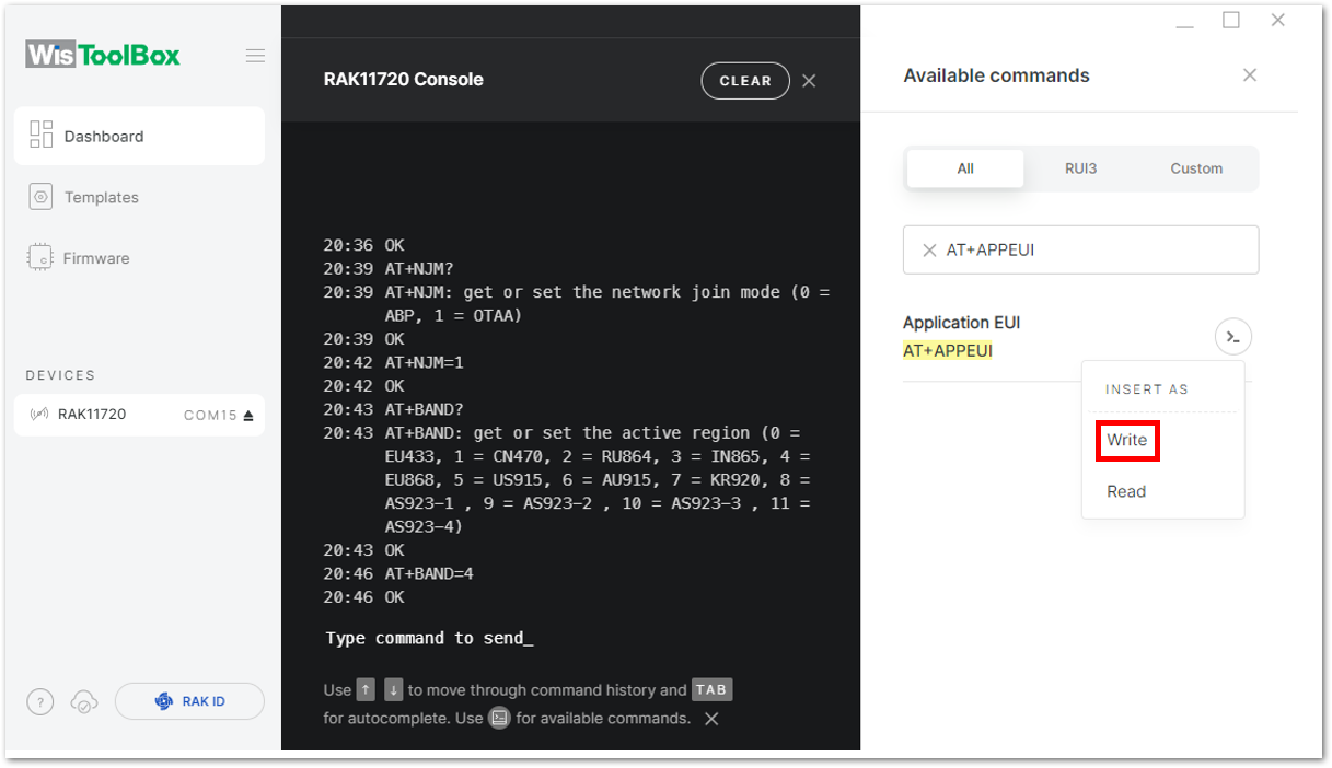 Figure 1: Insert AT+APPEUI command in the console
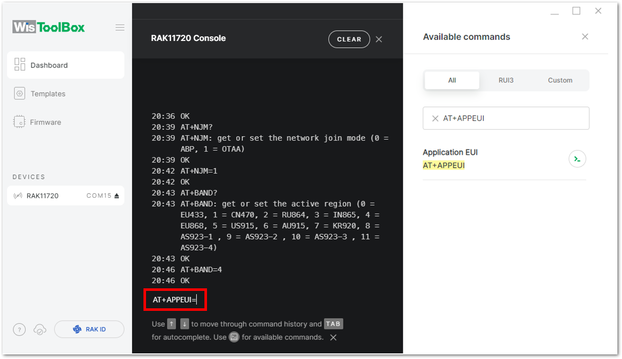 Figure 1: AT+APPEUI in the console
c. Paste the copied credential after the AT command into the WisToolBox console, and press Enter.
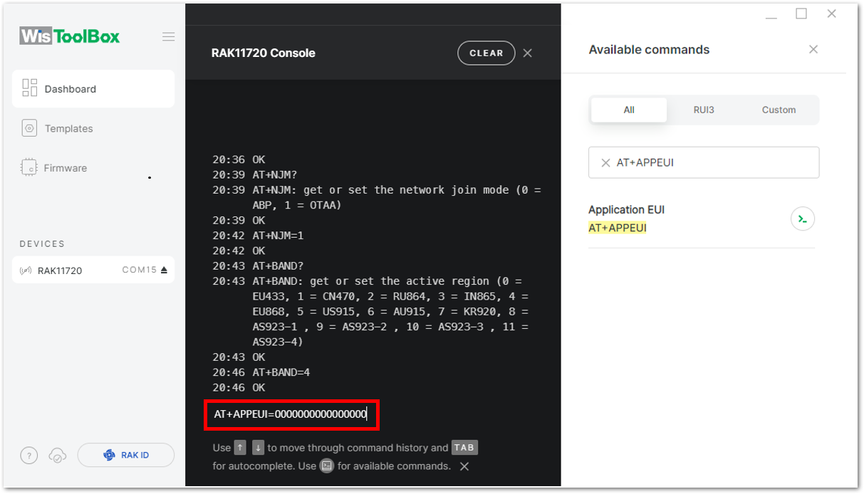 Figure 1: Paste AppEUI credential from TTN to the console
- After adding the AppEUI credential, do the same procedure for the Application key (AppKey) and the Device EUI (DevEUI).
a. Copy the AppKey credential, as shown in Figure 98.
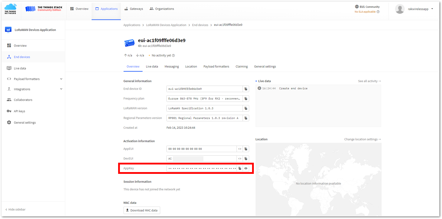 Figure 1: Copy the AppKey credential from TTN
b. Go to the WisToolBox console and write the AT+APPKEY command, as shown in Figure 99 to Figure 101.
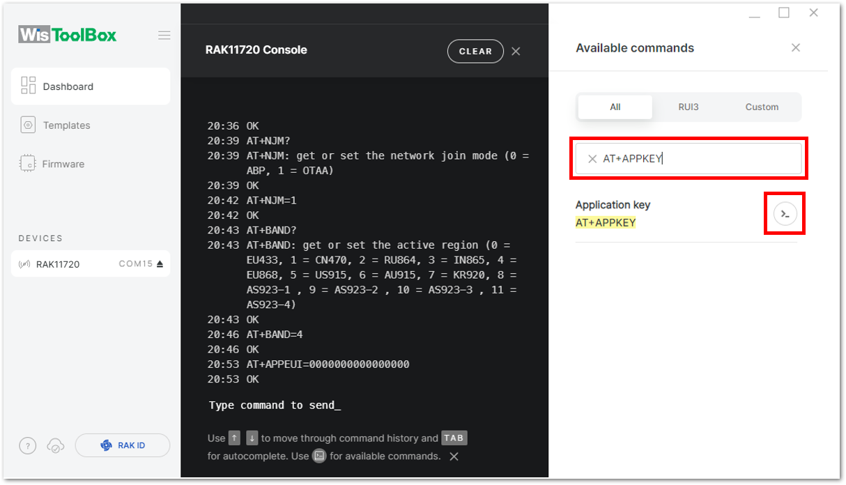 Figure 1: Search for the AppKey command
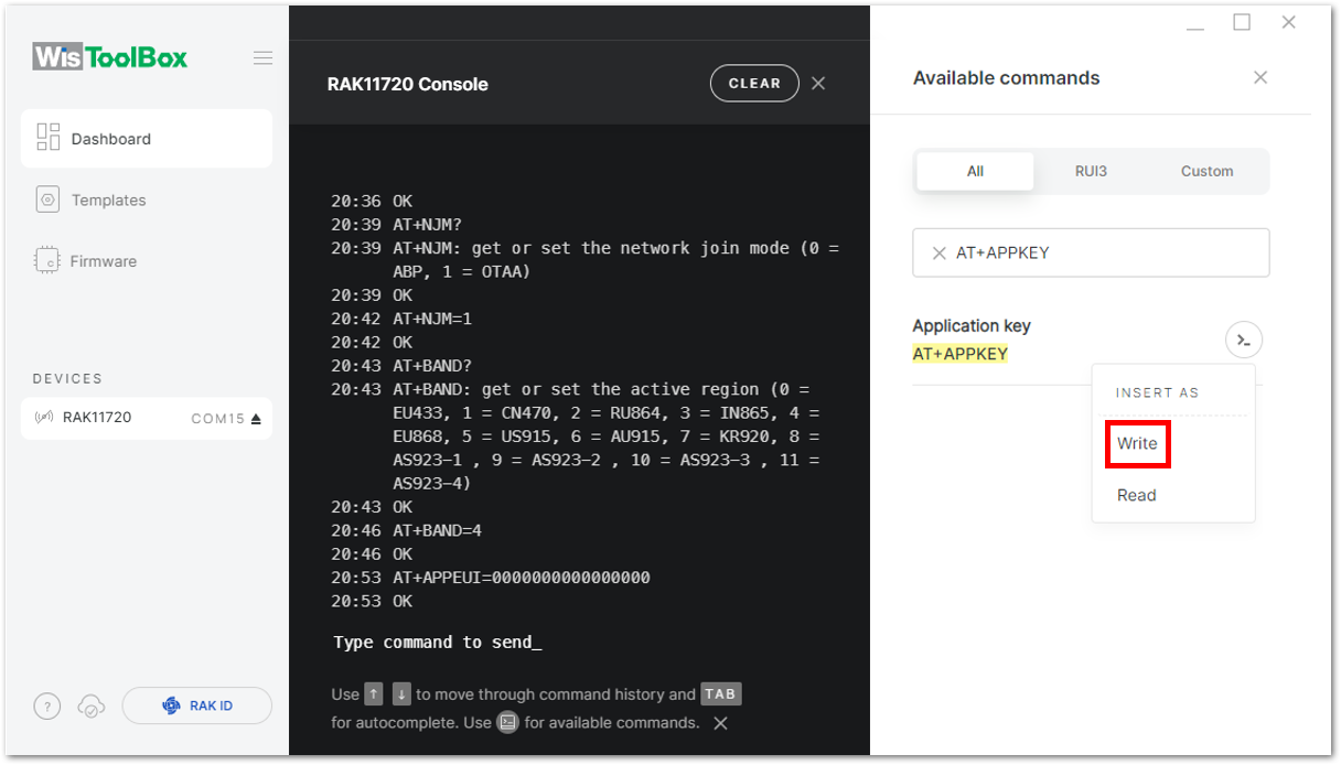 Figure 1: Insert AT+APPKEY command in the console
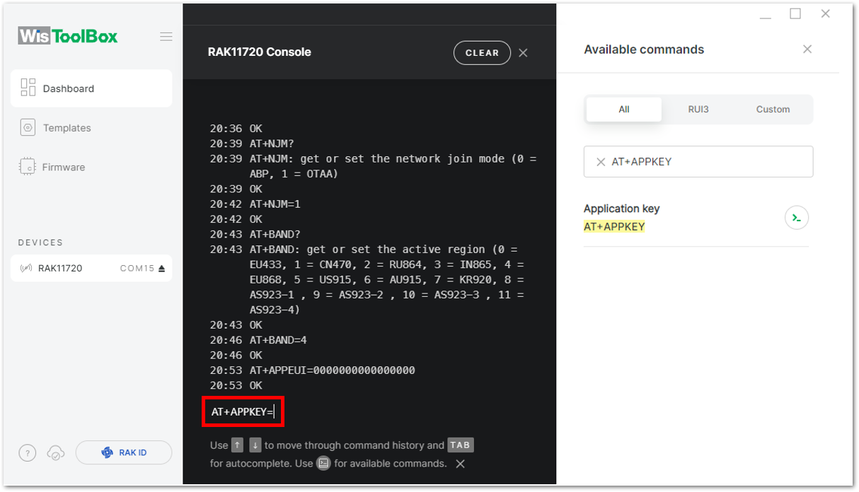 Figure 1: AT+APPKEY in the console
c. Paste the copied credential after the AT command, as shown in Figure 102, and press Enter.
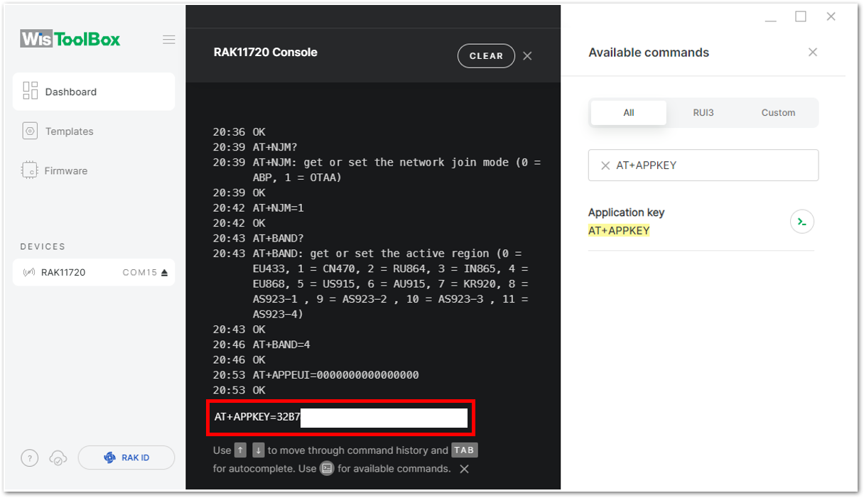 Figure 1: Paste AppKey credential from TTN to the console
a. Copy the DevEUI credential, as shown in Figure 103.
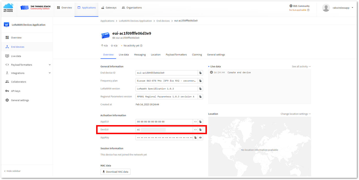 Figure 1: Copy the DevEUI credential from TTN
b. Go to the WisToolBox console and write the AT+DEVEUI command, as shown in Figure 104 to Figure 105.
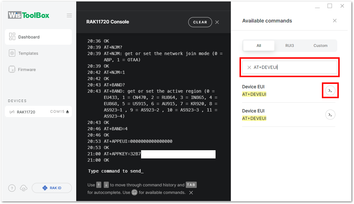 Figure 1: Search for the AT+DEVEUI command
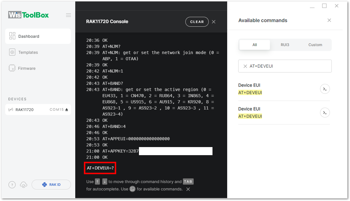 Figure 1: AT+DEVEUI in the console
c. Paste the copied credential after the AT command, as shown in Figure 106, and press Enter.
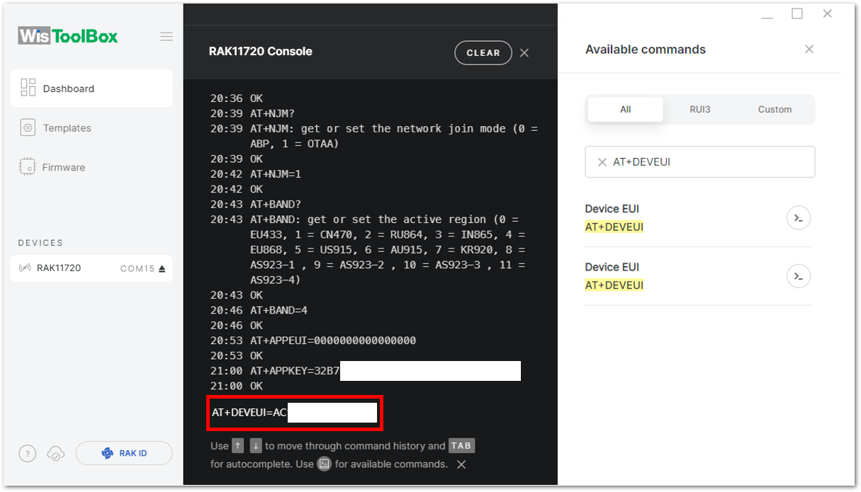 Figure 1: Paste DevEUI credential from TTN to the console
- With the OTAA device set up using the WisToolBox console, it is ready to join the network. Open the WisToolBox console, enter
AT+JOIN, change it toAT+JOIN=1, and press Enter to initiate the connection.
AT+JOINcommand parameters are optional. Configure the settings for auto-join, reattempt interval, and the number of join attempts if your application needs them. If not configured, it will use the default parameter values.AT+JOINandAT+JOIN=1also share the common functionality of trying to join the network.
Join command format: AT+JOIN=w:x:y:z
| Parameter | Description |
|---|---|
| w | Join command - 1: joining, 0: stop joining. |
| x | Auto-join config - 1: auto-join on power-up, 0: no auto-join |
| y | Reattempt interval in seconds (7-255) - 8 is the default. |
| z | Number of join attempts (0-255) - 0 is the default. |
After 5 ~ 6 seconds, if the request is successfully received by a LoRa gateway, a +EVT:JOINED status reply will appear.
- If the OTAA device failed to join, check if your device is within reach of a working LoRaWAN gateway that is configured to connect to TTN. It is also important to check that all your OTAA parameters (DevEUI, APPEUI, and AppKey) are correct using the
AT+DevEUI=?,AT+APPEUI=?, andAT+AppKey=?commands. Lastly, ensure that the antenna of your device is properly connected. - After checking all the things above, try to join again.
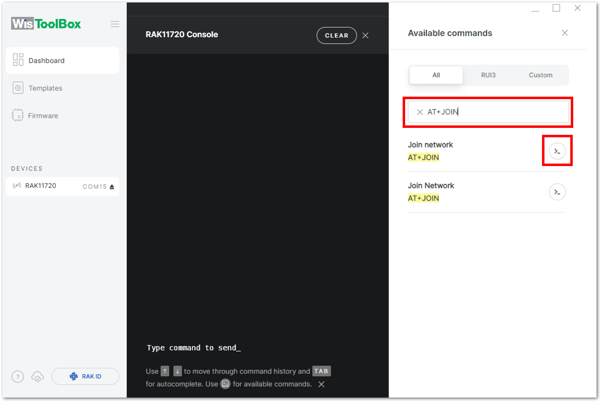 Figure 1: Search for the AT+JOIN command
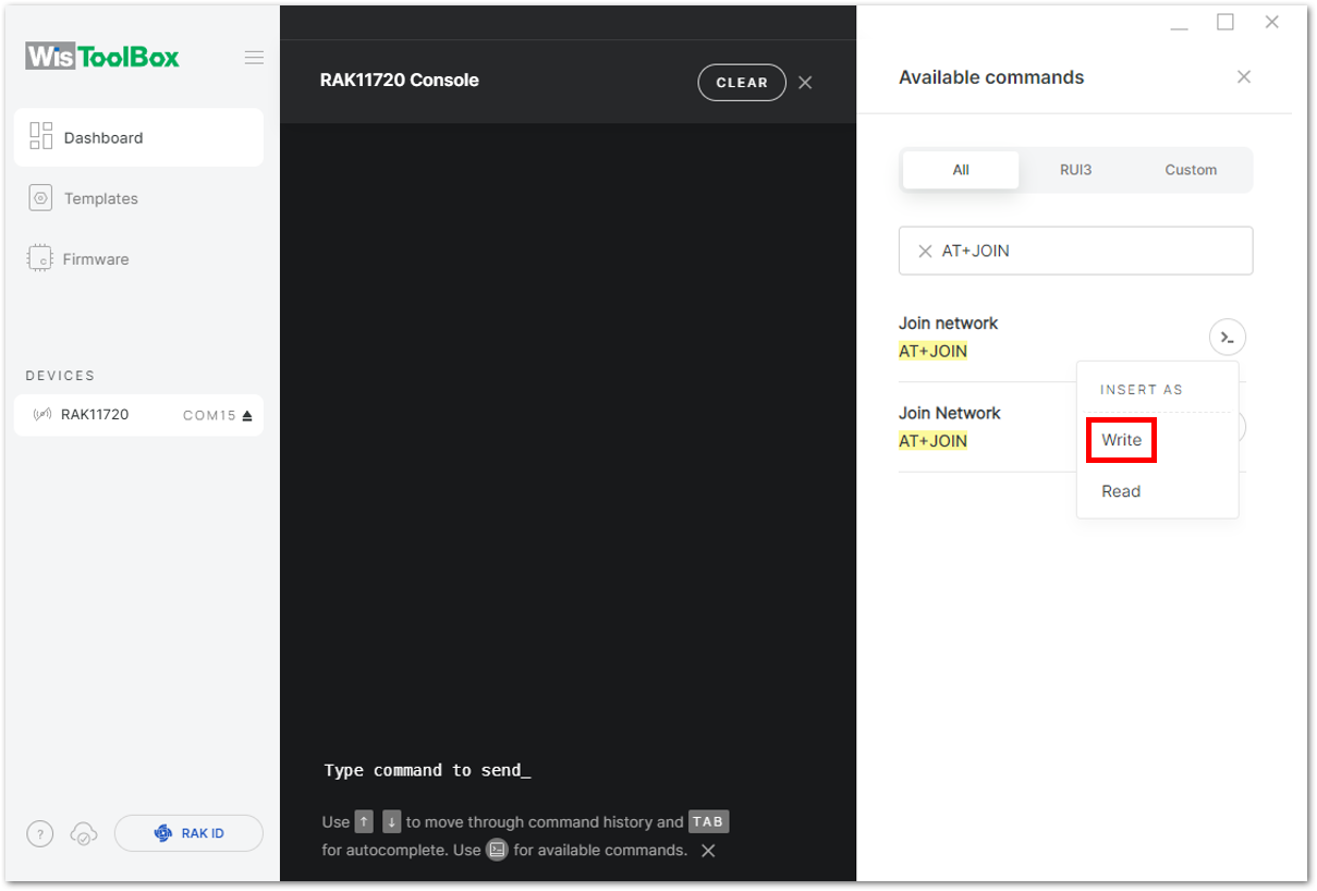 Figure 1: Insert AT+JOIN command in the console
 Figure 1: AT+JOIN in the console
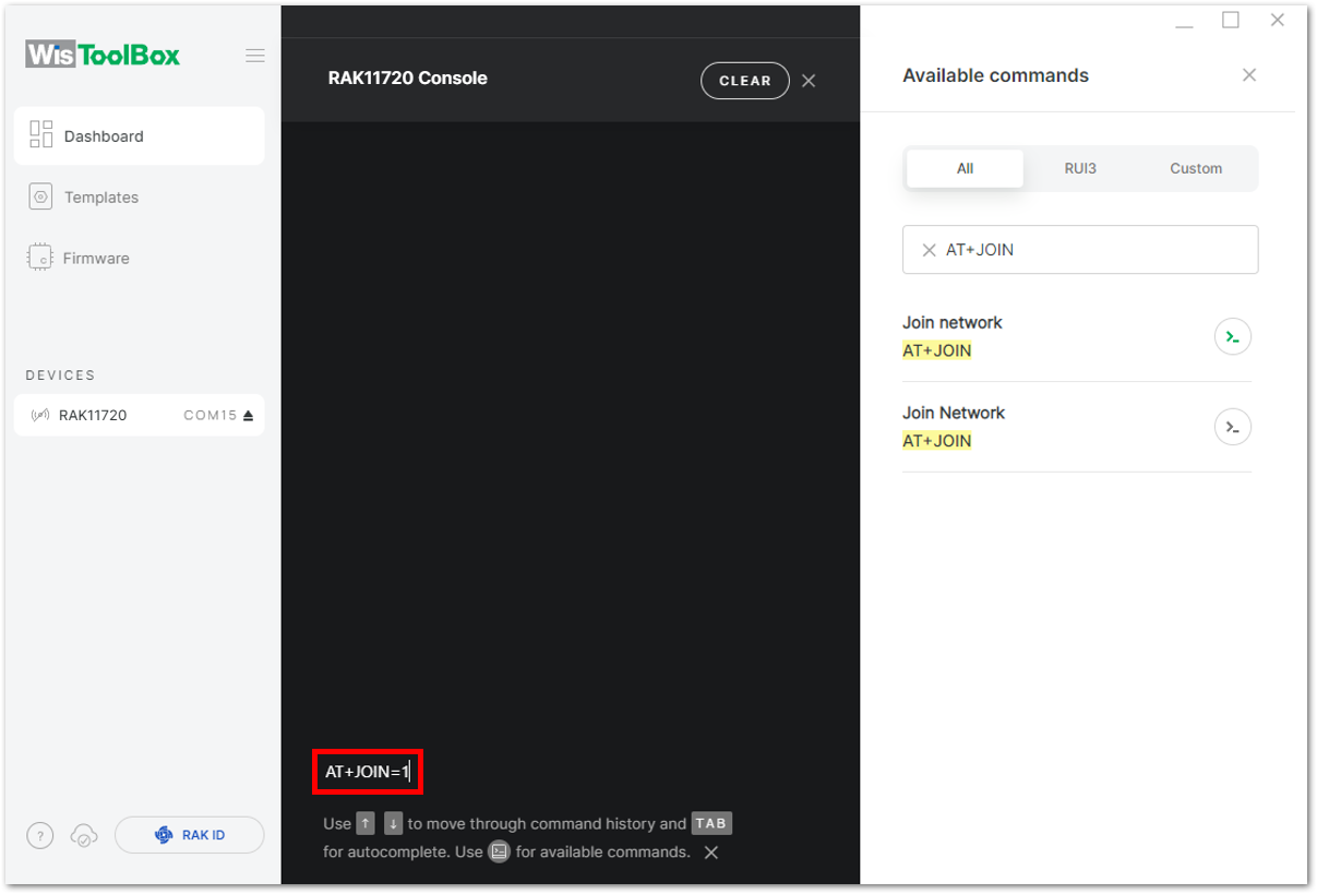 Figure 1: Join blocking mode
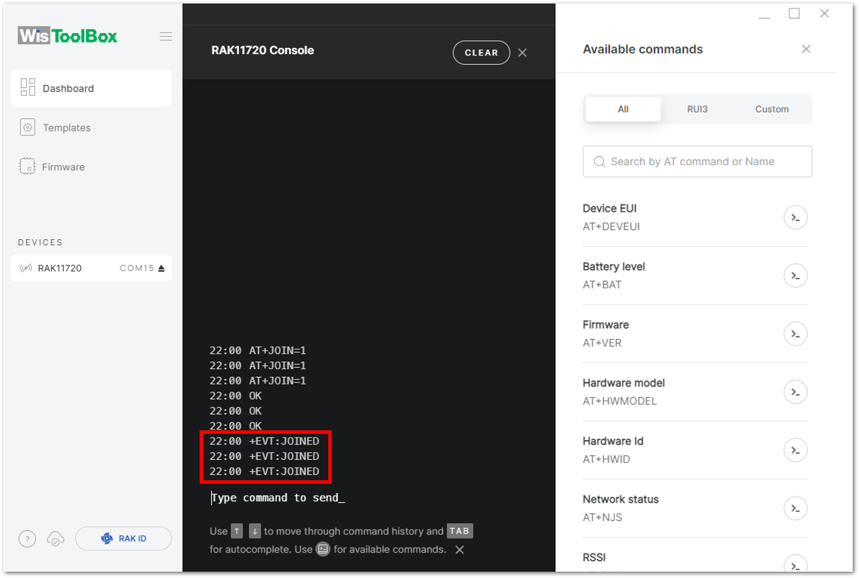 Figure 1: OTAA device successfully joined the networkFigure 1: OTAA device join process displayed in TTN Live data
- With the end-device properly joined to the TTN, try to send some payload after a successful join.
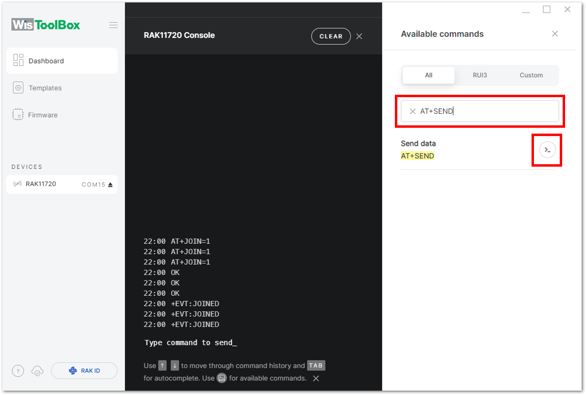 Figure 1: Search for the AT+SEND command
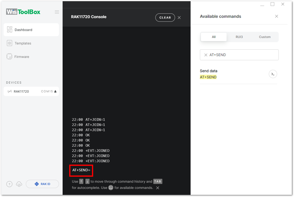 Figure 1: Insert AT+SEND command in the console
Send command format: AT+SEND=<port>:<payload>
AT+SEND=2:12345678
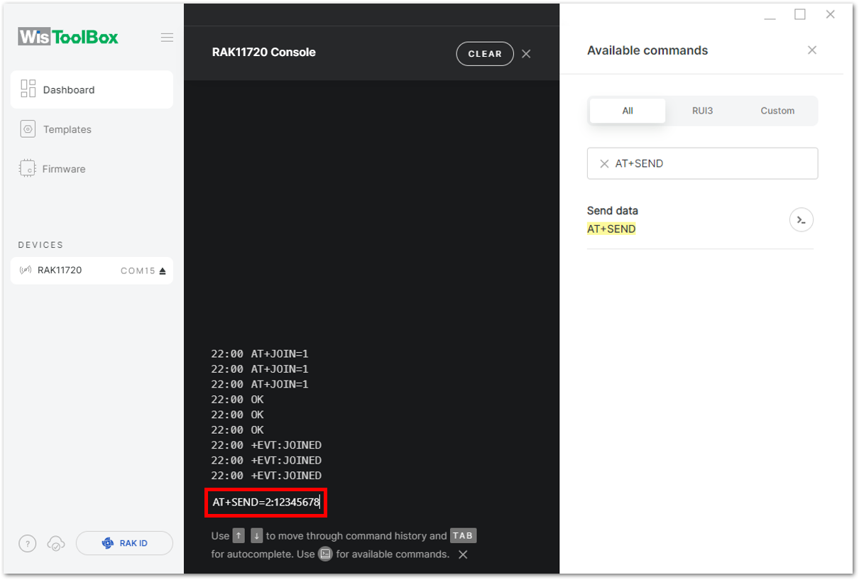 Figure 1: Add the port and payload
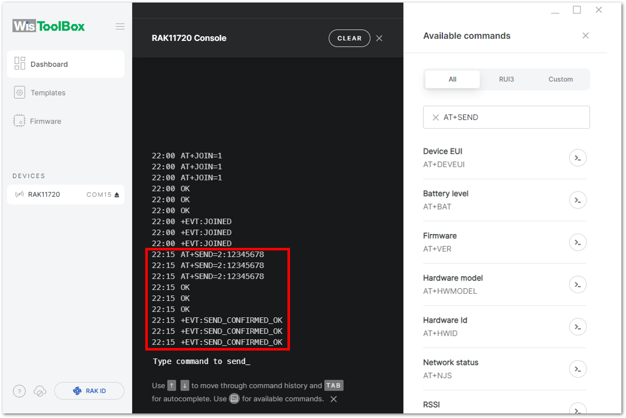 Figure 1: Transmission log confirmation
The data sent by the RAK11160 module appears in the Live data section of the TTN device console. Additionally, the Last seen timestamp should reflect activity from a few seconds or minutes ago.
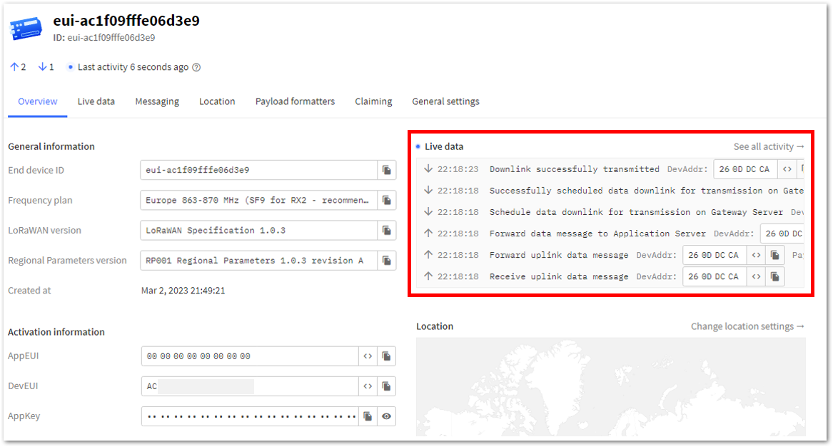 Figure 1: OTAA test data sent and displayed in TTN Live data
ABP Configuration for TTN via WisToolBox Console
This section shows the ABP configuration guide using WisToolBox console. Below are the steps for setting up your RAK11160 using WisToolBox Console.
- To begin the configuration, type
ATEto enable command echoing. Then, press Enter.
It is recommended to start by testing the console and verifying that the current configuration is working by sending these two AT commands:
AT
ATE
ATE is useful for tracking the commands and troubleshooting.
You will receive OK when you input the two commands. After setting ATE, see all the commands you input together with the replies.
If there is no OK or any reply, check if the device is powered correctly. If you are getting power from a USB port, ensure that you have a good USB cable.
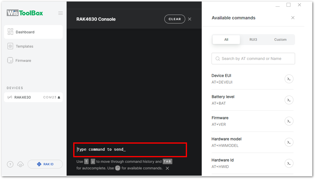 Figure 1: Type a command to send
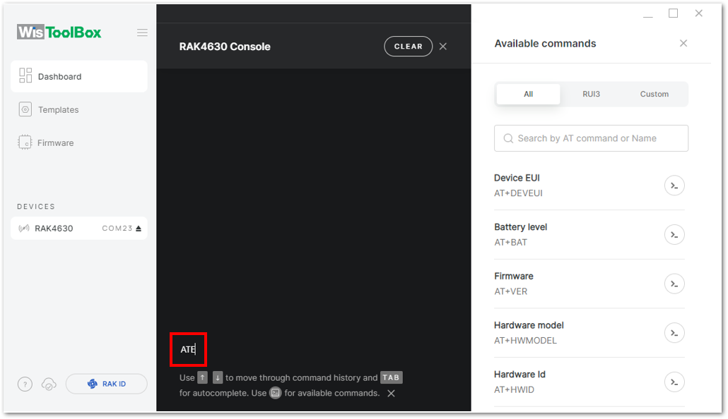 Figure 1: Enable local echoing
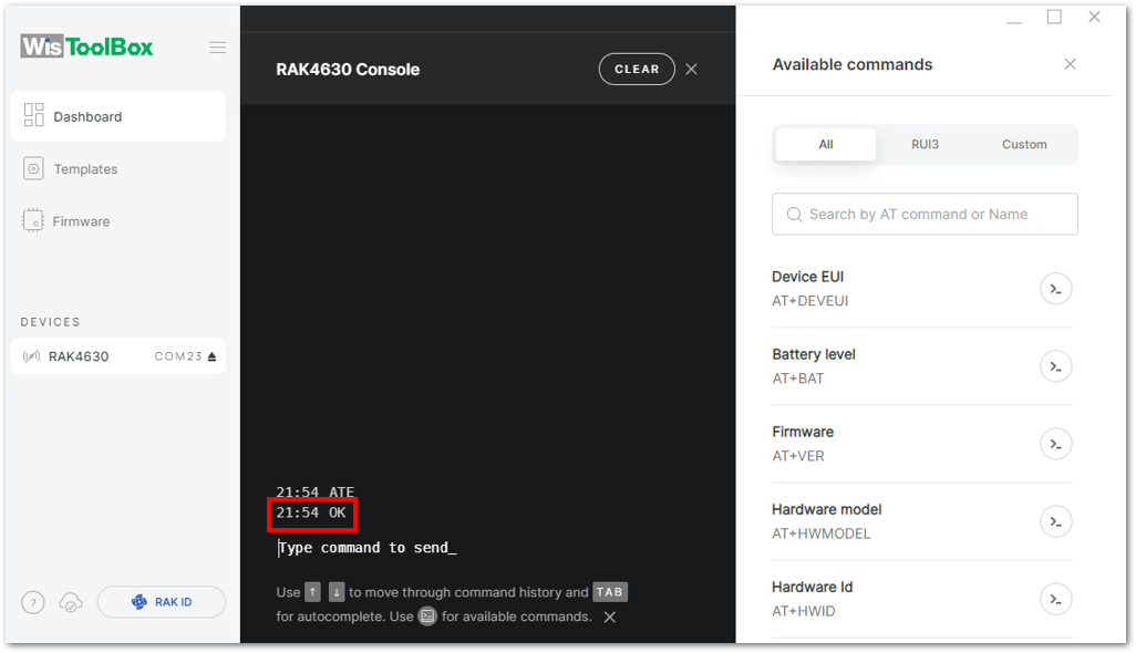 Figure 1: Local echoing enabled
- Set the LoRaWAN join mode to ABP. To determine the required parameter, type
AT+NJM?in the console terminal and press Enter.
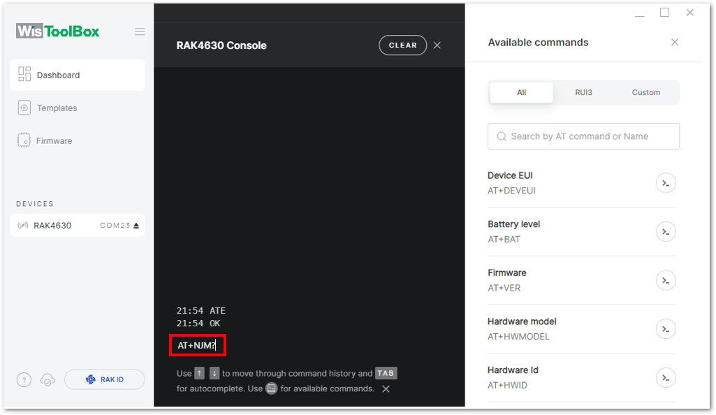 Figure 1: Join mode query
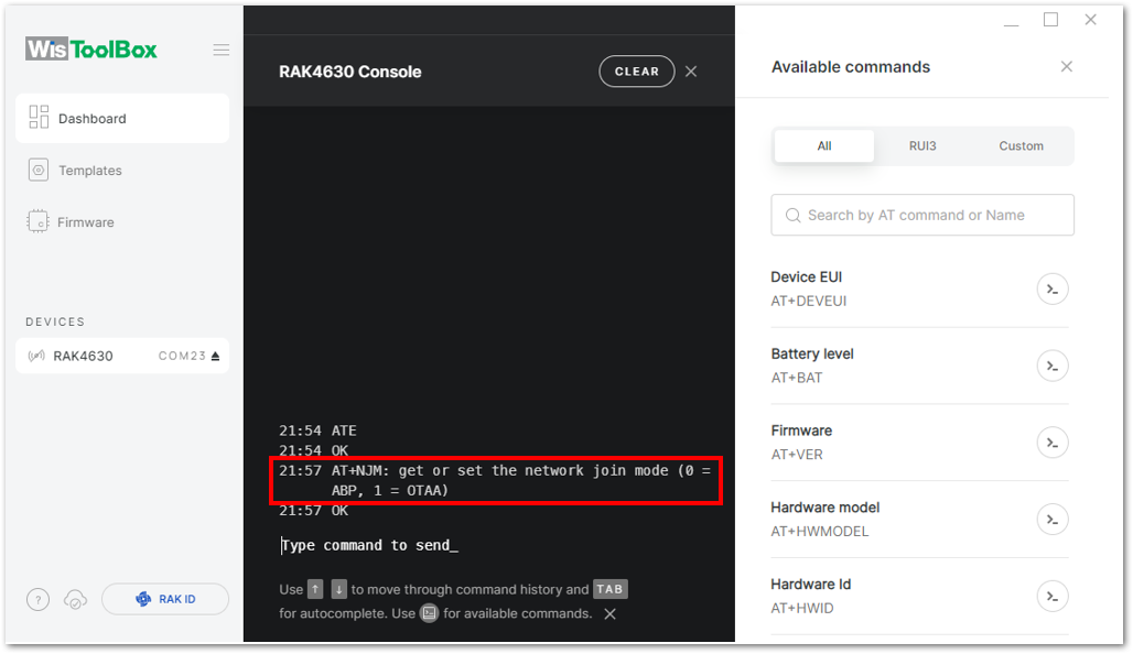 Figure 1: Join mode options
- For ABP, input
AT+NJM=0and then press Enter, as shown in Figure 123.
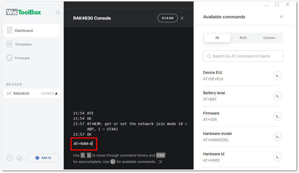 Figure 1: ABP join mode
- Once done, set the LoRaWAN region to EU868. To verify the required parameter, type
AT+BAND?in the console terminal and press Enter.
AT+BAND=4
- Based on the selected Regional Band, configuring the sub-band on the RAK11160 may be necessary to ensure compatibility with the gateway and LoRaWAN network server. This is particularly important for bands such as US915, AU915, and CN470.
- To configure the masking of channels for the sub-bands, use the
AT+MASKcommand that can be found on the AT Command Manual. - To illustrate, use sub-band 2 by sending the command
AT+MASK=0002.
| Code | Regional Band |
|---|---|
| 0 | EU433 |
| 1 | CN470 |
| 2 | RU864 |
| 3 | IN865 |
| 4 | EU868 |
| 5 | US915 |
| 6 | AU915 |
| 7 | KR920 |
| 8 | AS923-1 |
| 9 | AS923-2 |
| 10 | AS923-3 |
| 11 | AS923-4 |
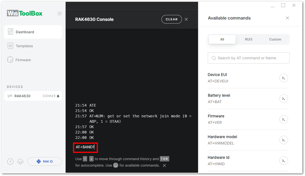 Figure 1: Frequency band query
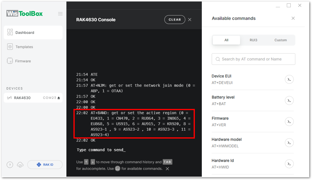 Figure 1: Frequency band options
- For EU868, enter
AT+BAND=4and press Enter. For other regional bands, refer to the List of band parameter options table below.
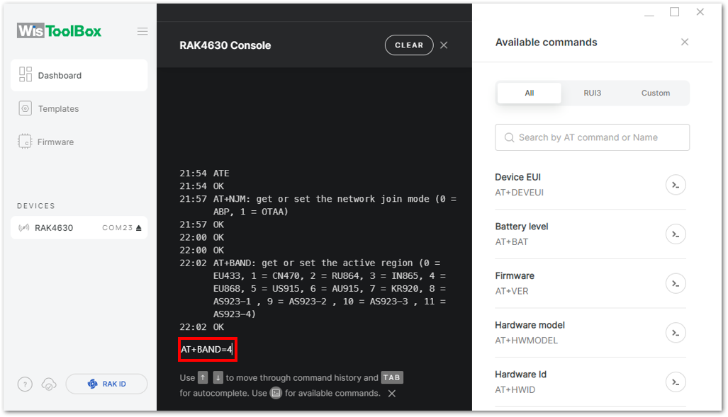 Figure 1: EU868 frequency band
- Update the ABP credentials of the device. Open the console where the RAK11160 end device was created, copy the specific Activation information needed.
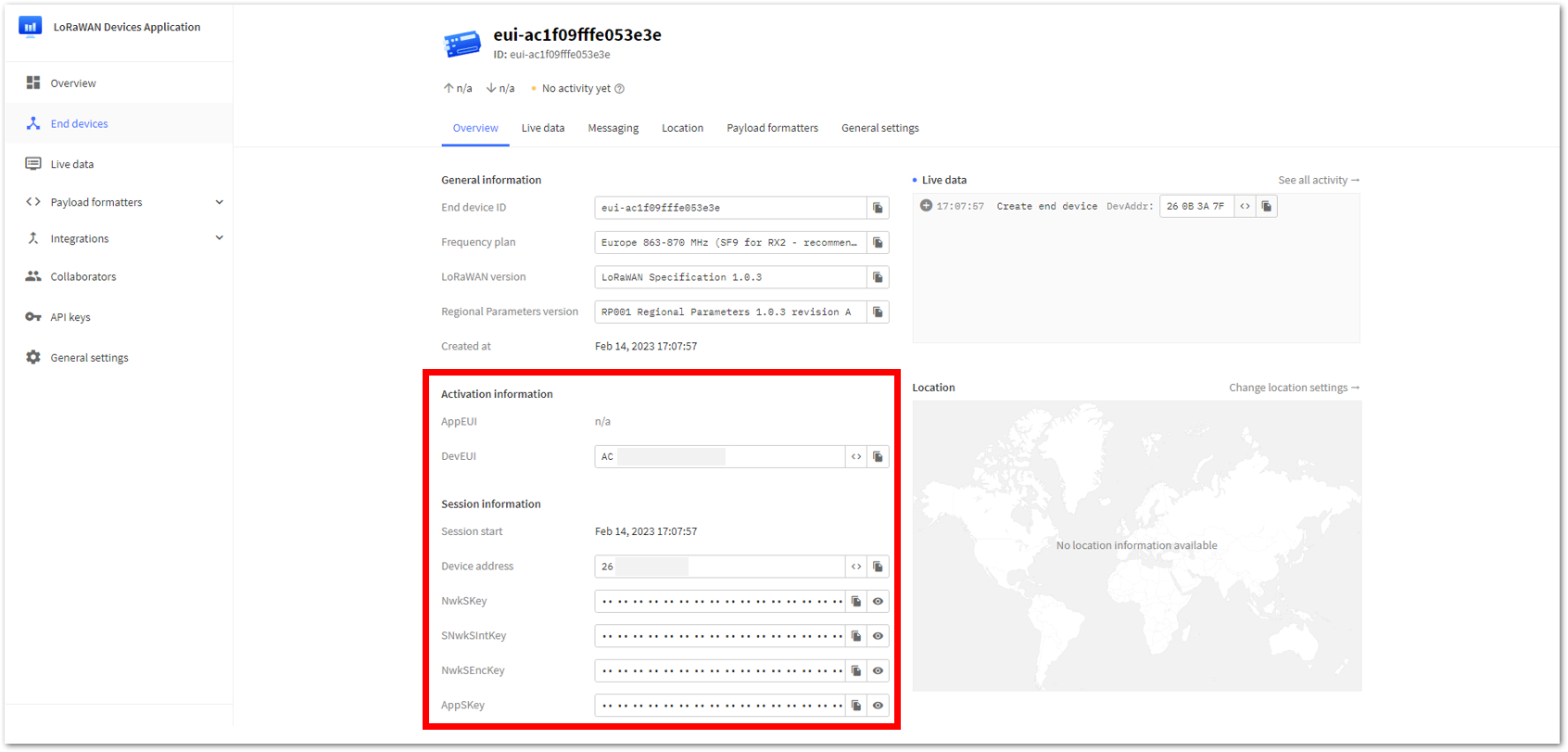 Figure 1: Your created ABP device overview in the TTN Console
a. Copy the AppSKey credential, as shown in Figure 128.
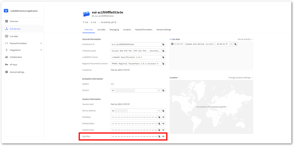 Figure 1: Copy the AppSKey credential from TTN
b. Go to the WisToolBox console and write the appropriate AT command.
- For the AppSKey, write the
AT+APPSKEYcommand, as shown in Figure 129 to Figure 131.
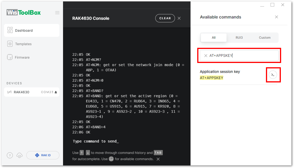 Figure 1: Search for the AppSKey command
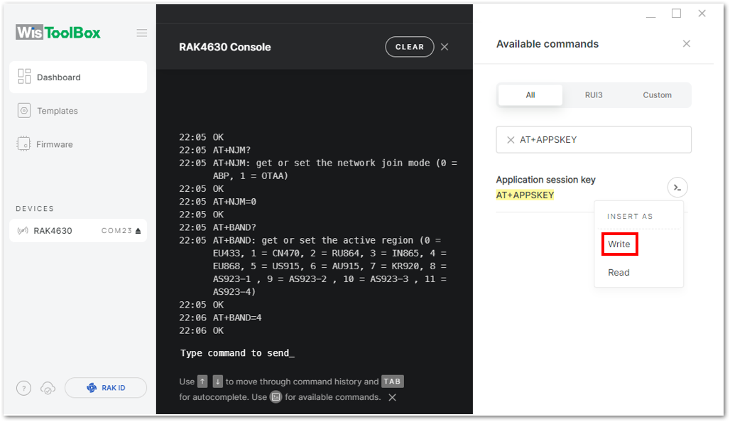 Figure 1: Insert AT+APPSKEY command in the console
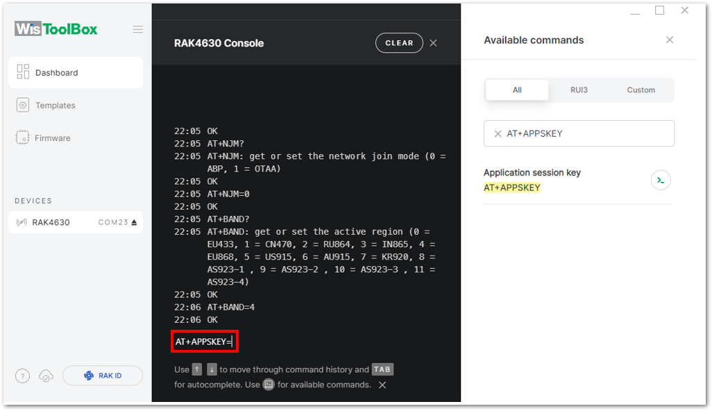 Figure 1: AT+APPSKEY in the console
c. Paste the copied credential after the AT command into the WisToolBox console, and press Enter.
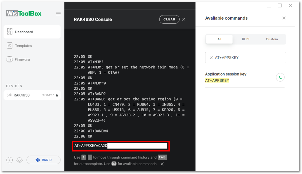 Figure 1: Paste AppKey credential from TTN to the console
- After adding the AppSKey credential, do the same procedure for the Device address and the Network session key (NwkSKey).
a. Copy the Device address, as shown in Figure 133.
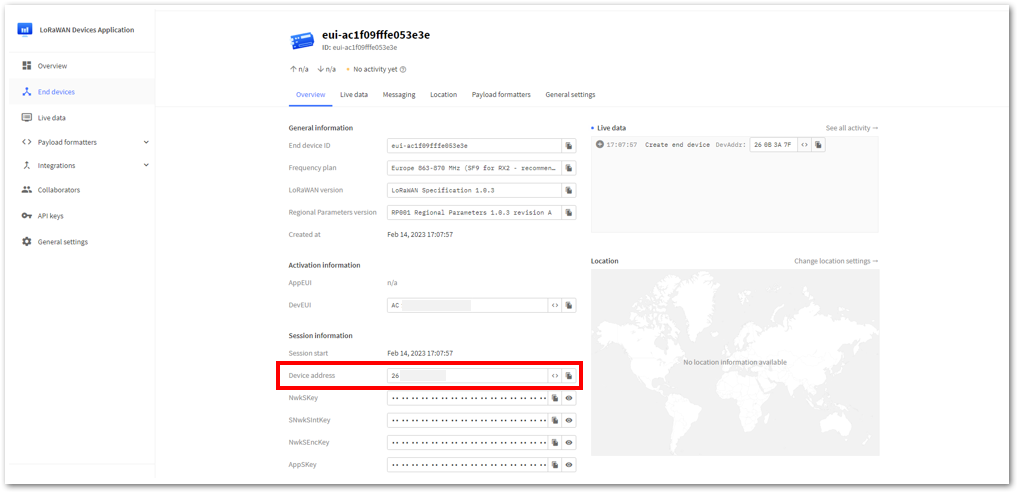 Figure 1: Copy the Device Address credential from TTN
b. Go to the WisToolBox console and write the AT+DEVADDR command, as shown in Figure 134 to Figure 136.
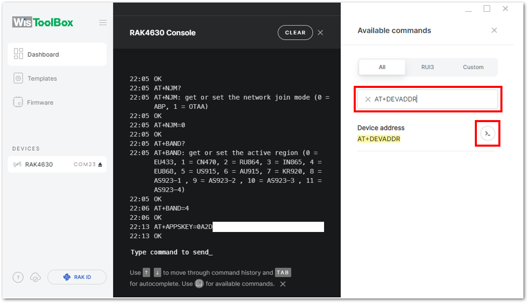 Figure 1: Search for the Device Address command
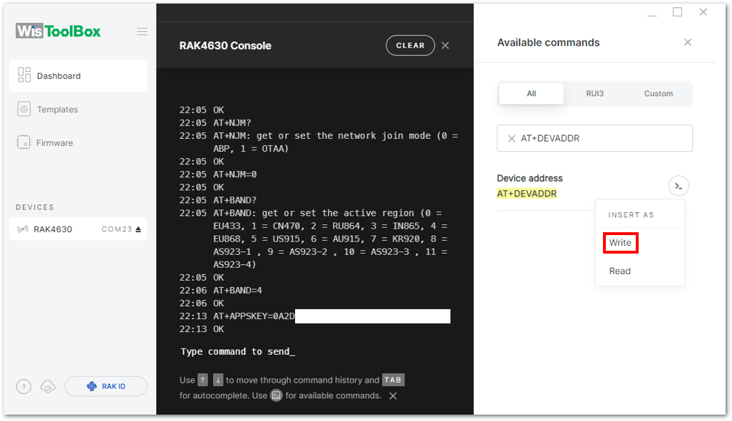 Figure 1: Insert AT+DEVADDR command in the console
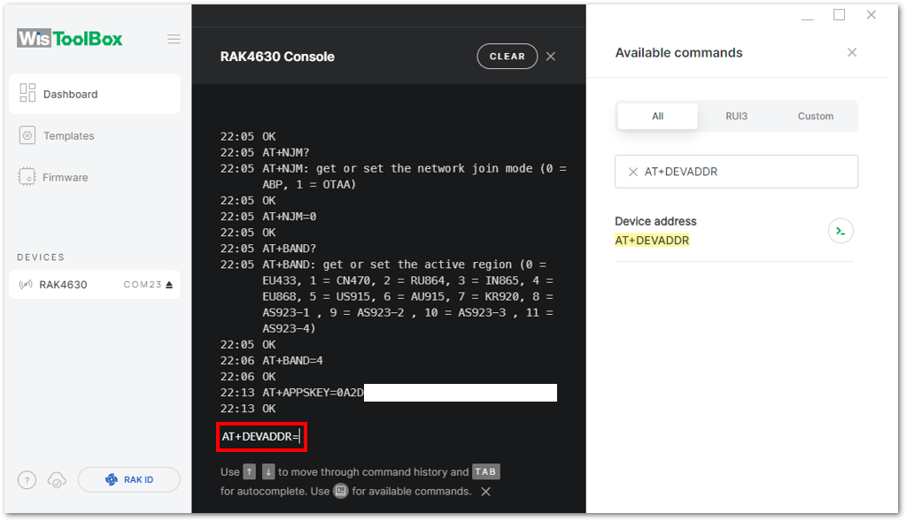 Figure 1: AT+DEVADDR in the console
c. Paste the copied credential after the AT command, as shown in Figure 137, and press Enter.
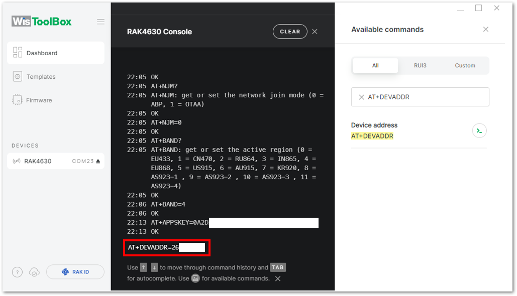 Figure 1: Paste Device address from TTN to the console
a. Copy the NwkSKey credential, as shown in Figure 138.
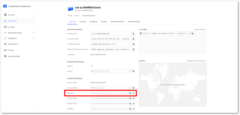 Figure 1: Copy the NwkSKey credential from TTN
b. Go to the WisToolBox console and write the AT+NWKSKEY command, as shown in Figure 139 to Figure 141.
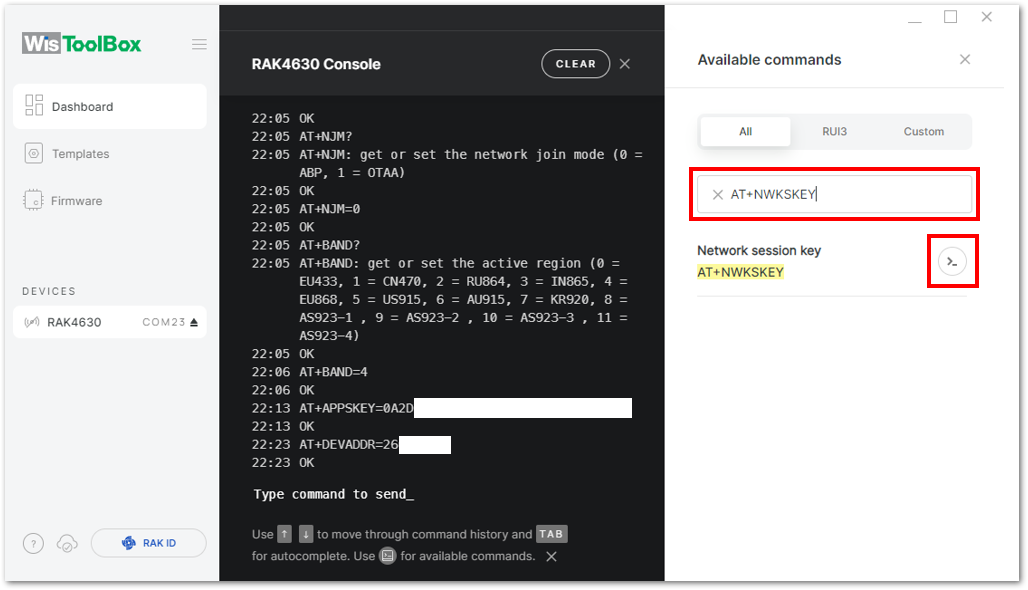 Figure 1: Search for the AT+NWKSKEY command
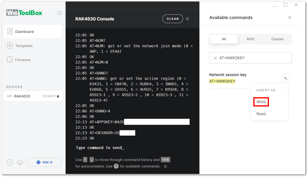 Figure 1: Insert AT+NWKSKEY command in the console
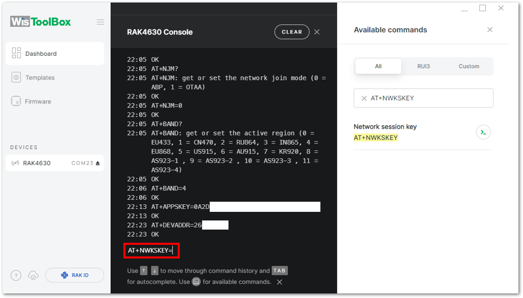 Figure 1: AT+NWKSKEY in the console
c. Paste the copied credential after the AT command, as shown in Figure 142, and press Enter.
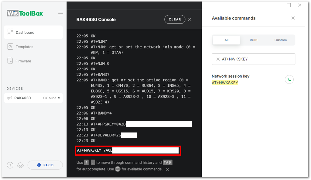 Figure 1: Paste NwkSKey credential from TTN to the console
- With the ABP device configured using the WisToolBox console, it is now directly connected to the network, eliminating the need for a joining procedure. To test data transmission, reopen the WisToolBox terminal console and send a payload to TTN.
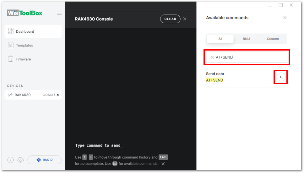 Figure 1: Search for the AT+SEND command
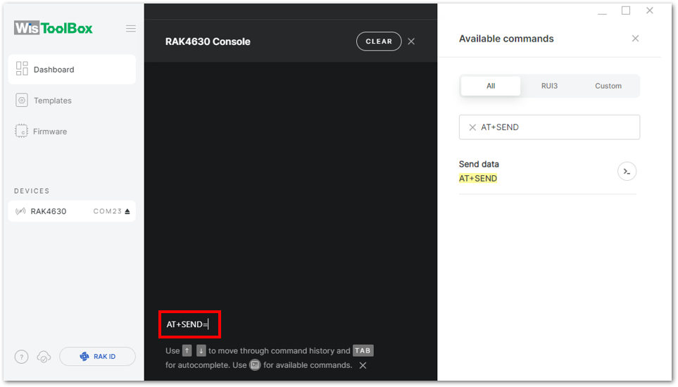 Figure 1: Insert AT+SEND command in the console
Send command format: AT+SEND=<port>:<payload>
AT+SEND=2:12345678
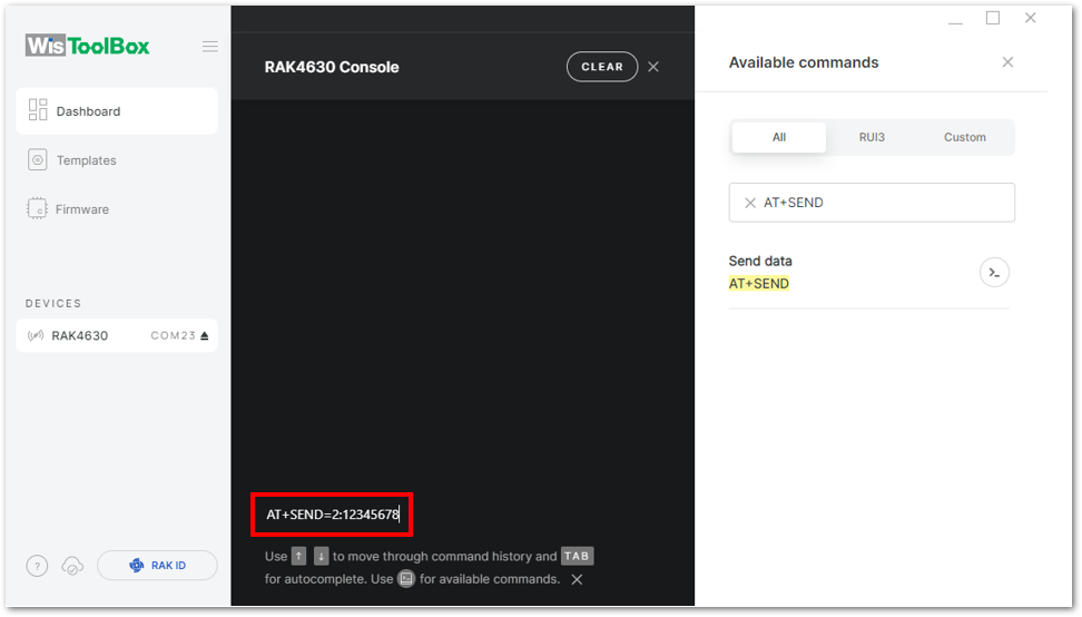 Figure 1: Add the port and payload
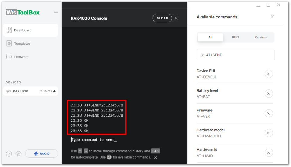 Figure 1: Transmission log confirmation
The data sent by the RAK11160 module appears in the Live data section of the TTN device console. Additionally, the Last seen timestamp should reflect activity from a few seconds or minutes ago.
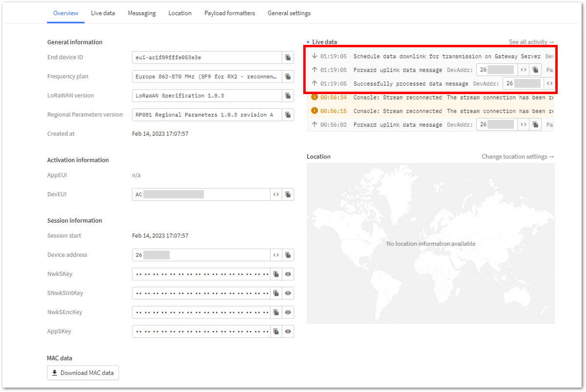 Figure 1: ABP test data sent and displayed in TTN Live data
LoRa P2P Mode
This section shows how to set up and connect two RAK11160 units to work in the LoRa P2P mode. The configuration of the RAK11160 units is done by connecting the two modules to a general-purpose computer using a USB-UART converter. The setup of each RAK11160 can be done separately, but testing the LoRa P2P mode will require having both units connected simultaneously. This could be done by having one computer with two USB ports or two computers with one USB port each.
It is recommended to start by testing the serial communication and verifying the current configuration is working by sending these two AT commands:
AT
ATE
ATE will echo the commands you input to the module, which is useful for tracking the commands and troubleshooting.
You will receive OK when you input the two commands. After setting ATE, see all the commands you input together with the replies.
Try again AT and you should see it on the terminal followed by OK.
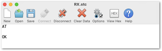 Figure 1: AT command response
- To set up the RAK11160 to work in LoRa P2P mode, input the work mode command on both RAK11160 modules. If sending commands via USB, disconnecting and reconnecting the module may be necessary as it switches modes of operation.
AT+NWM=0
- For this P2P setup, the LoRa parameters are the following:
- Link frequency: 868000000 Hz
- Spreading factor: 7
- Bandwidth: 125 kHz
- Coding Rate: 0 = 4/5
- Preamble Length: 10
- Power: 14 dBm
AT+P2P=868000000:7:125:0:10:14
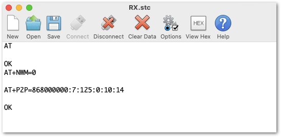 Figure 1: P2P setup
- To set one module as a receiver (RX), set the value of the P2P to receive a command to 65535.
AT+PRECV=65535
With one module configured as RX, the other device will be the TX. Try to sending a P2P payload.
AT+PSEND=11223344
- If the
AT+PRECVvalue is set to 65534, the device will continuously listen to P2P LoRa TX packets without any timeout. This is the same as setting the device in RX mode. - If the
AT+PRECVvalue is set to 65535, the device will listen to P2P TX without a timeout. But it will stop listening once a P2P LoRa packet is received to save power. - If the
AT+PRECVvalue is 0, the device will stop listening to P2P TX data. The device is in TX mode.
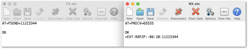 Figure 1: Sent and received P2P LoRa Packets
Wi-Fi Example with AT Commands
The ESP8684 co-processor is handling the Wi-Fi and BLE communication. The STM32WLE5 can communicate with the ESP8684 with AT commands through its internal UART.
The Espressif AT command manual can be found on Espressif's website in ESP-AT User Guide.
There are many options to setup the ESP8684, only the basic commands are shown here. For a full description how to control the ESP8684, please check the Espressif AT command manual.
To send AT commands from the console or an external host MCU, you have to change the UART mode of the STM32WLE5 to loop-through mode. This is done with the AT command AT+ESP=x
To enable loop-through mode:
AT+ESP=1
To disable loop-through mode:
AT+ESP=0
Connect to a Wi-Fi AP
To connect to a Wi-Fi AP, the ESP8684 must be set to station mode. Then the AP name and AP access password must be provided. The AP name and AP access password are stored in the ESP8684 and will be reused on the next reboot/power up to automatically connect Wi-Fi.
Connect to a Wi-Fi AP and enable auto-connect:
AT+ESP=1

AT+CWMODE=1,1
AT+CWJAP="<MQTT_WIFI_APN>","<MQTT_WIFI_PW>"
Replace <MQTT_WIFI_APN> and <MQTT_WIFI_PW> with the AP name and access credential of the Wi-Fi access point.
If the ESP8684 can successfully connect to the Wi-Fi AP, it will response with
WIFI DISCONNECT
WIFI CONNECTED
WIFI GOT IP

OK
Connect to a MQTT Broker Through Wi-Fi
To connect to the MQTT broker two AT commands are required to setup the connection.
Define user:
AT+MQTTUSERCFG=0,1,"<MQTT_USER>","<MQTT_USERNAME>","<MQTT_PASSWORD>",0,0,""
Replace <MQTT_USER>, <MQTT_USERNAME> and <MQTT_PASSWORD> with the user ID, username and password required to connect.
Define connection and start connection:
AT+MQTTCONN=0,"<MQTT_URL>",<MQTT_PORT>,0
Replace <MQTT_URL> and <MQTT_PORT> with the URL or IP address of the MQTT broker and the used port.
If the setup and connection is successful, the ESP8684 will response with OK and +MQTTCONNECTED:
AT+MQTTUSERCFG=0,1,"<MQTT_USER>","<MQTT_USERNAME>","<MQTT_PASSWORD>",0,0,""

OK

AT+MQTTCONN=0,"<MQTT_URL>",<MQTT_PORT>,0
+MQTTCONNECTED:0,1,"<MQTT_URL>","<MQTT_PORT>","",0

OK
Then it is possible to publish data with:
AT+MQTTPUB=0,"<MQTT_PUB>","<data>",0,0
Replace <MQTT_PUB>with the topic the data should be published to
Replace <data> with a string with the data to be published.
It is as well possible to subscribe to a topic on the MQTT broker with:
AT+MQTTSUB=0,"<MQTT_TOPIC>",1
Replace <MQTT_TOPIC>with the topic to subscribe to.
The received data of the subscription will be reported by the ESP8684 with an asynchronous event. To receive this event, the loop-through of the ESP8684 to the host MCU must stay enabled.
Miscellaneous
Upgrade the Firmware
To upgrade the module to the latest firmware version, follow the steps in this section. The latest firmware can be found in the software section of RAK11160 Datasheet.
What if the RAK11160 module stops responding to AT commands and firmware updates?
To recover your device, use the .hex file found in the datasheet and upload it using STM32CubeProgrammer. The guide on updating STM32 firmware using STM32CubeProgrammer can be found in the How To Guide: STM32CubeProgrammer for RAK Modules.
Uploading the .hex file via STM32CubeProgrammer will erase all configured data on the device.
Firmware Upgrade Through UART2
Minimum Hardware and Software Requirements
Refer to the table for the minimum hardware and software required to perform the firmware upgrade via UART2:
| Hardware/Software | Requirement |
|---|---|
| Computer | A Windows/Ubuntu/Mac computer |
| Firmware File | Bin firmware file downloaded from the website |
| Others | A USB to TTL module |
Firmware Upgrade Procedure
Execute the following procedure to upgrade the firmware in Device Firmware Upgrade (DFU) mode through the UART2 interface.
- The RAK11160 should automatically enter BOOT mode when firmware is uploaded via RAK DFU Tool or WisToolBox.
- If BOOT mode is not initiated, manually send
AT+BOOTcommand to start bootloader mode.
-
Download the latest application firmware of the RAK11160.
Refer to the table below:
| Model | Version | Source |
|---|---|---|
| RAK11160 (.bin) | RUI3 Application Code only (default baudrate = 115200) | Download |
| RAK11160 (.hex) | RUI3 Bootloader and Application Code (default baudrate = 115200) | Download |
-
Download the RAK Device Firmware Upgrade (DFU) tool.
-
Connect the RAK11160 module with a computer through a USB to TTL.
-
Open the RAK Device Firmware Upgrade Tool. Select the serial port and baud rate (115200) of the module and click the Select Port button.
- If the firmware upload repeatedly fails, check your current baud rate setting using the
AT+BAUD=?command and use that baud rate value in the RAK DFU Tool. - Another option is to check if you selected the right COM port.
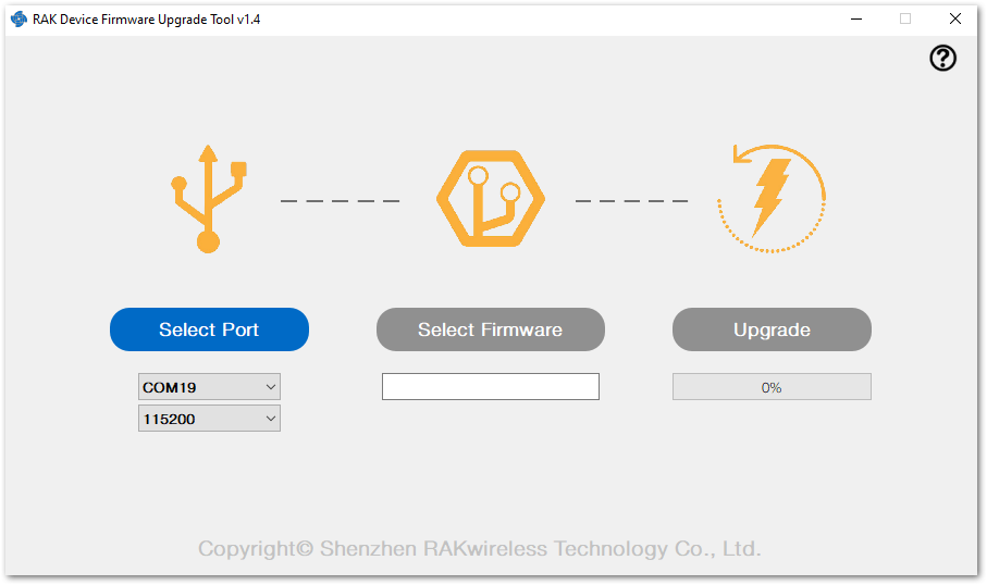 Figure 1: RAK Device Firmware Upgrade Tool
- Select the application firmware file of the module with the suffix .bin.
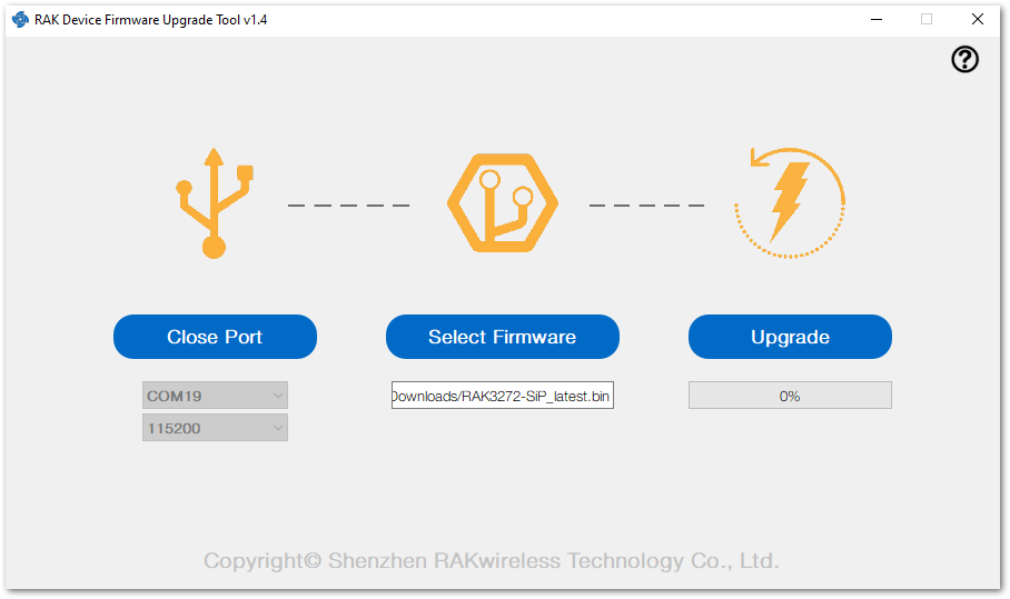 Figure 1: Select firmware
- Click the Upgrade button to upgrade the device. After the upgrade is complete, the RAK11160 will be ready to work with the new firmware.
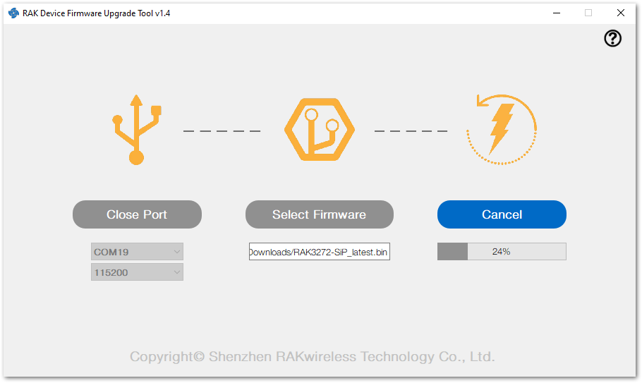 Figure 1: Upgrade firmware
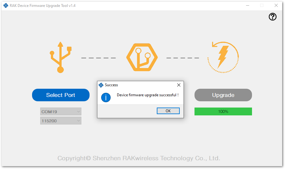 Figure 1: Upgrade successful
Arduino Installation
Refer to Software section.