RAK7268V2/RAK7268CV2 WisGate Edge Lite 2 Quick Start Guide
This manual provides brief instructions for installing and deploying the gateway.
Prerequisites
- RAK7268V2/RAK7268CV2 WisGate Edge Lite 2
-
Ethernet Cable (RJ-45 Port) for Ethernet connection
-
A Windows/MacOS/Linux Computer
-
Installation Accessories (e.g., mounting kit, power supply, screws, etc.)
-
NanoSIM Card (for LTE version) – If you're using the cellular version of the gateway, ensure you have a SIM card ready for installation. Size: 12 x 9 x 0.67 mm.
Package Inclusion
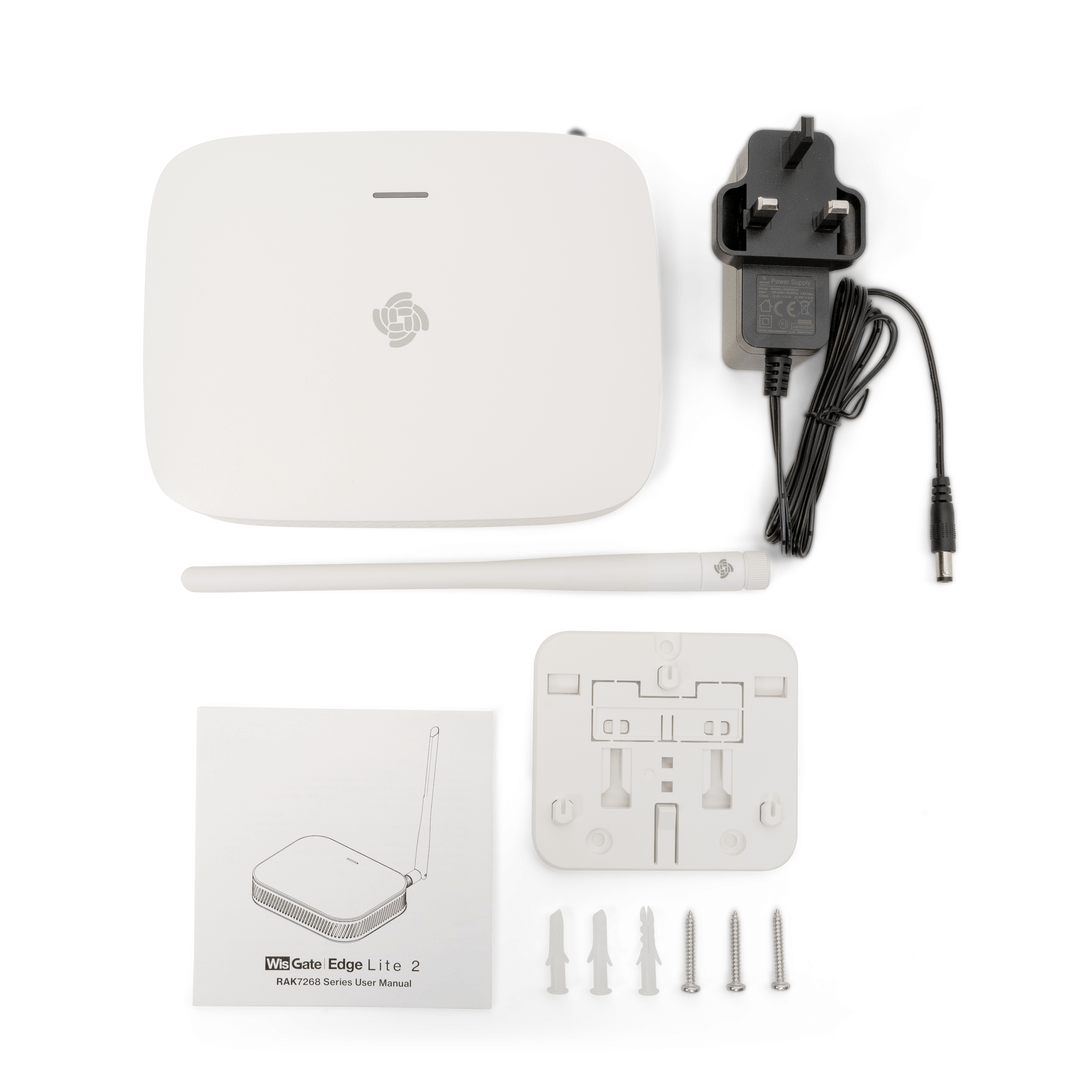 Figure 1: RAK7268V2/RAK7268CV2 package contents
- 1pc Gateway
- 1pc LoRa antenna
- 1pc Power supply
- 1pc mounting bracket
Product Configuration
Gateway Installation Guide
Do not eject the SD card located in the SD card slot during installation, as it stores logs and data essential for the device's performance.
Insert SIM Card
If you are using the cellular variant of the gateway, refer to this section. Otherwise, skip it.
The SIM card slot of the cellular versions is not hot-swappable. Make sure the gateway is switched off before inserting or ejecting the SIM card.
- On the front of the gateway, locate the NanoSIM card slot.
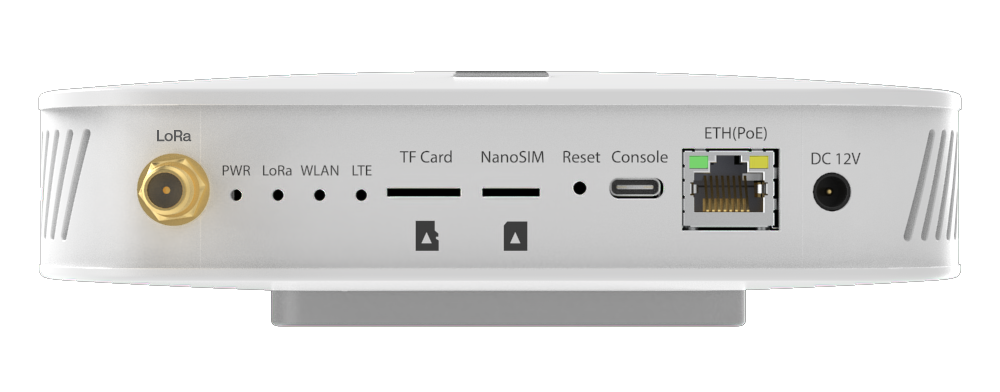 Figure 1: Inserting SIM card
- Insert the NanoSIM card into the slot, ensuring it is securely seated.
Mount the Bracket
The gateway supports wall-mounting, ceiling-mounting, and rail-mounting. You can choose one according to your needs.
Wall Mounting
- Use a 5-millimeter drill bit to drill three (3) holes on a wall. It is recommended to mark the location of the holes on the wall before drilling.
- Insert the expansion tubes into the drilled holes.
- Secure the bracket to the wall using screws through the holes in the bracket.
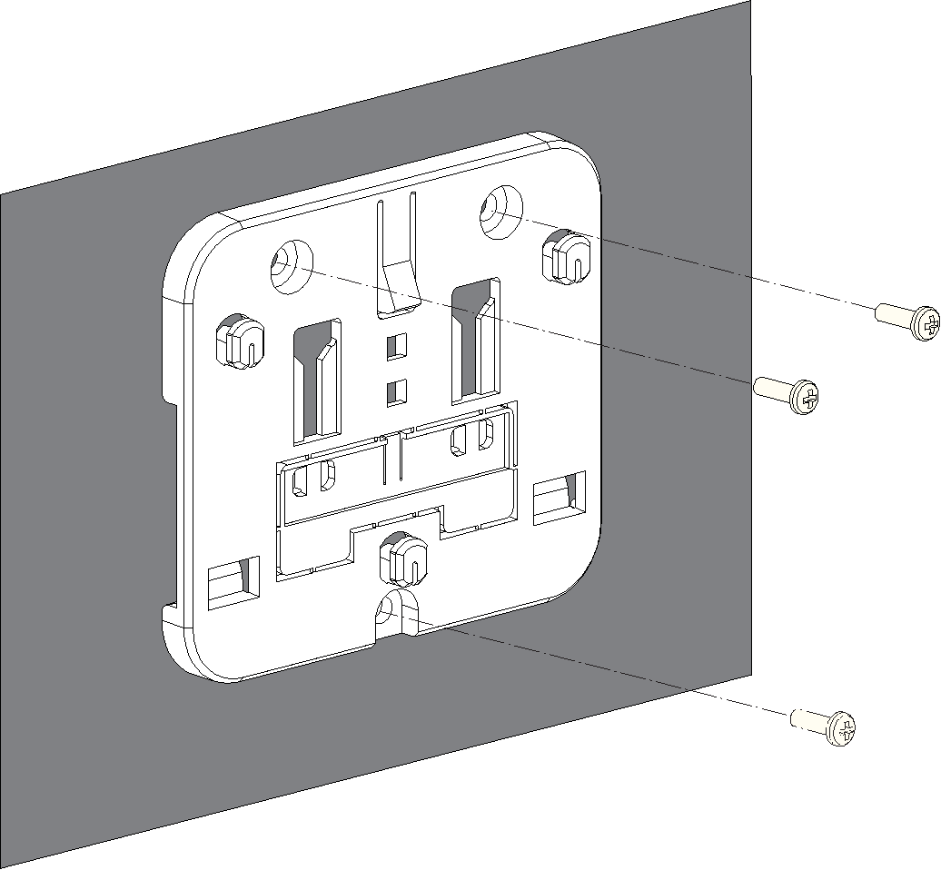 Figure 1: Mounting bracket
Ceiling Mounting
For ceiling mounting, you need to choose a ceiling that is strong enough to support the gateway. It is recommended to mark the hole locations on the ceiling before installing the bracket.
-
Choose self-tapping screws or expansion tubes and self-tapping screws to install the bracket according to the actual material of the ceiling.
-
(Optional) Refer to this step when installing the bracket using expansion tubes and self-tapping screws. Otherwise, skip it.
-
Use a 5-millimeter drill bit to drill three (3) holes in the ceiling.
-
Insert the expansion tubes into the holes drilled in the ceiling.
-
-
Secure the bracket to the ceiling using self-tapping screws through the holes in the bracket.
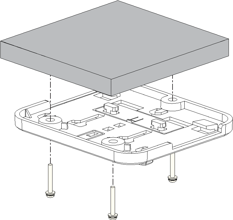 Figure 1: Mounting bracket
T-Shaped Keel Mounting
In this section, a T-shaped keel is used as an example. You can choose other types of rails for installation.
The bracket supports rail widths of 14 mm, 16 mm and 24 mm.
- Remove the mounting clip from the bracket.
- Insert one side of the T-shaped keel into the two clips of the bracket.
- Insert the two T-shaped hooks on the mounting clip into the T-shaped rails of the bracket, slide the mounting clip to the other side of the T-shaped keel, and make sure the clip is in place.
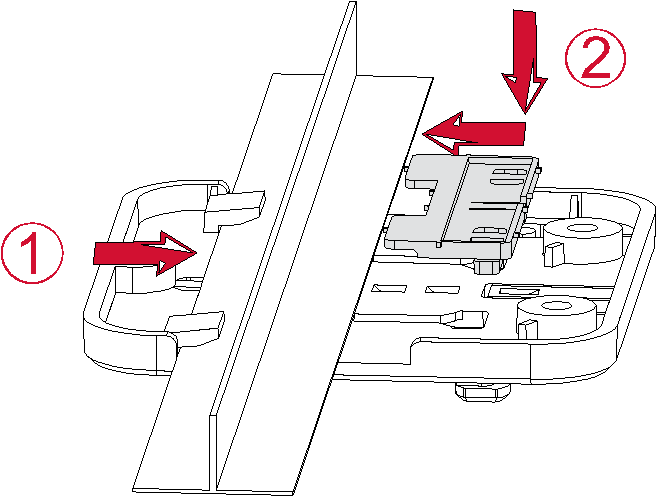 Figure 1: Mounting bracket
Install the Gateway
- Align the lower edge of the gateway's hanging hole with the bracket's locking plate.
- Move the gateway closer to the bracket so that the bracket's locking plate enters the gateway's hanging hole.
- Pull the gateway to ensure that the gateway is in place.
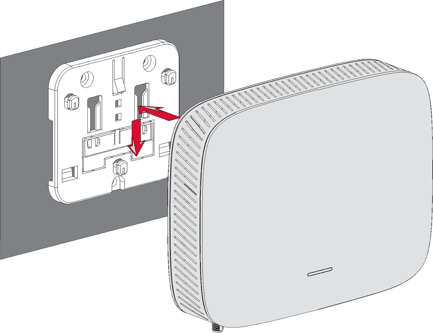 Figure 1: Fixed gateway
Attach the Antenna
Attach the LoRa antenna by screwing it onto the RP-SMA connector on the gateway.
Power On the Gateway
Do not power the device if the LoRa antenna port has been left open to avoid potential damage to the RAK7268V2/RAK7268CV2 WisGate Edge Lite 2.
The RAK7268V2/RAK7268CV2 can be powered using one of the following options:
- Power Adapter
- Connect the power adapter to the device.
- Plug the other end of the adapter into a power outlet.
- Power over Ethernet (PoE) (Optional, PoE injector not included in the shipment)
- Connect an Ethernet cable to the device's ETH(PoE) port.
- Ensure the PoE injector is properly connected and powered.
The PWR LED will turn on when the device is powered correctly.
Key LED Indicators After Power On
After powering on the gateway, confirm the operational status of the device using the following LED indicators. For more detailed LED information, refer to the datasheet.
- PWR LED (Power Indicator):
- Solid Green: The device is powered on and working correctly.
- Off: The device is not powered.
- LoRa LED:
- Solid Green: LoRa connection is active.
- Off: No LoRa connection.
- WLAN LED (Wi-Fi):
- Solid Green: The Access Point (AP) is active and broadcasting.
- OFF: The AP is not active.
- ETH LED (Ethernet):
- Solid Green: Ethernet connection is established.
- Off: No Ethernet connection.
- LTE LED (For RAK7268CV2 with LTE):
- Slow Flicker (1800 ms High / 200 ms Low): Network searching
- Slow flicker (200 ms High / 1800 ms Low): Idle
Access the Gateway
In this section, two methods of accessing the gateway are provided to offer different alternatives based on the availability of the required resources.
Wi-Fi AP Mode
By default, the gateway will work in Wi-Fi AP Mode which means that you can find an SSID named like "RAK7268V2_XXXX or RAK7268CV2_XXXX" on your PC's Wi-Fi Network List. "XXXX" is the last two bytes of the Gateway MAC address.
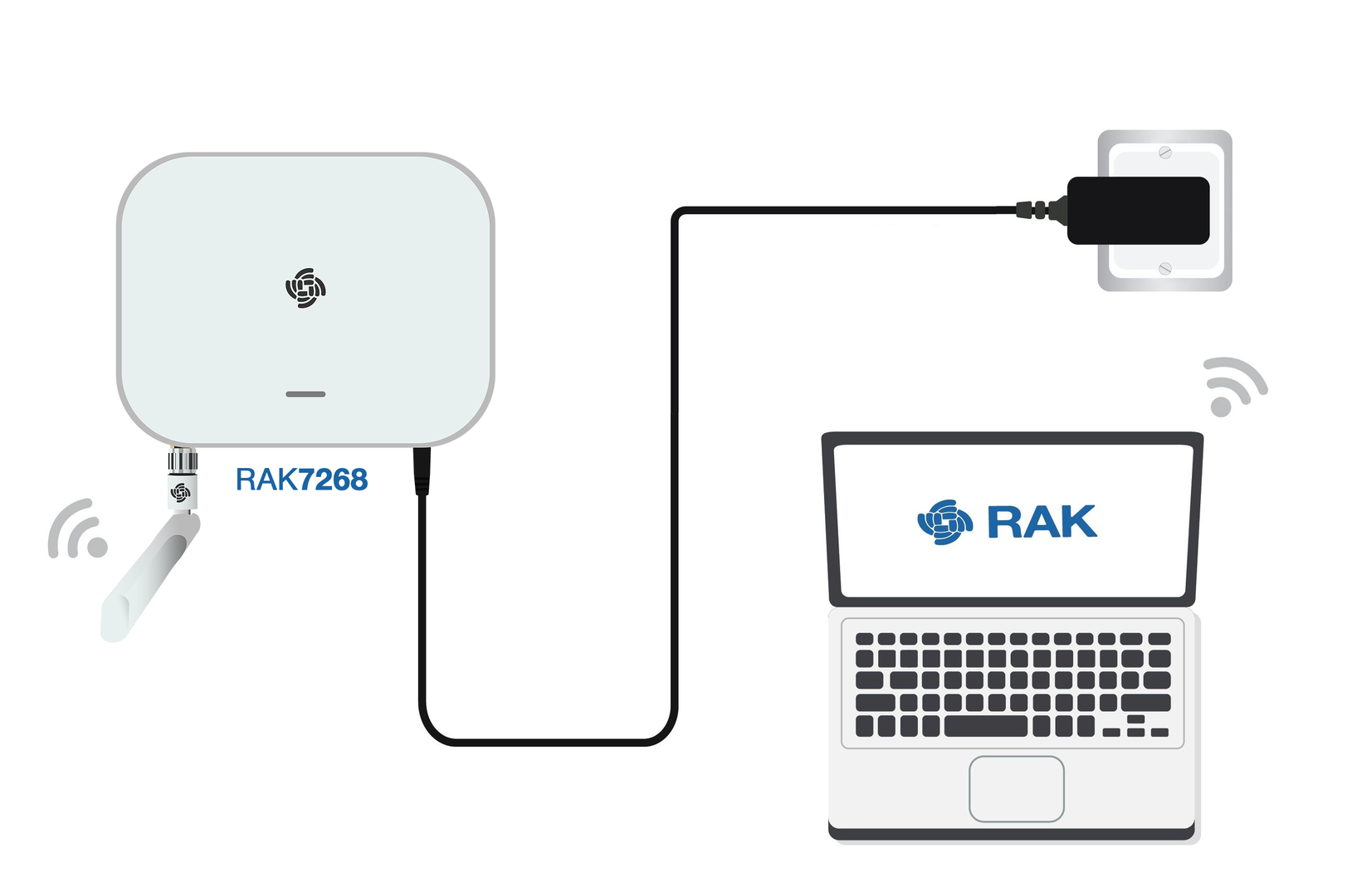 Figure 1: Accessing the gateway via Wi-Fi AP Mode
-
Connect to the gateway’s Wi-Fi.
NOTENo password is required to connect via Wi-Fi.
-
Open a web browser and enter the IP address:
192.168.230.1 -
On the first login, you must set a login password. The password must:
- At least 12 characters long
- Has at least one special character (
!“#$%&\‘()*+,-./:;<=>?@[]^_{|}~) - Has at least one number
- Has at least one standard Latin letter (used in the English alphabet)
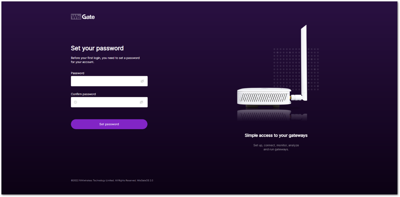 Figure 1: Web UI login page
- Click Set password to continue. You will be redirected to the LoRaWAN Statistics page.
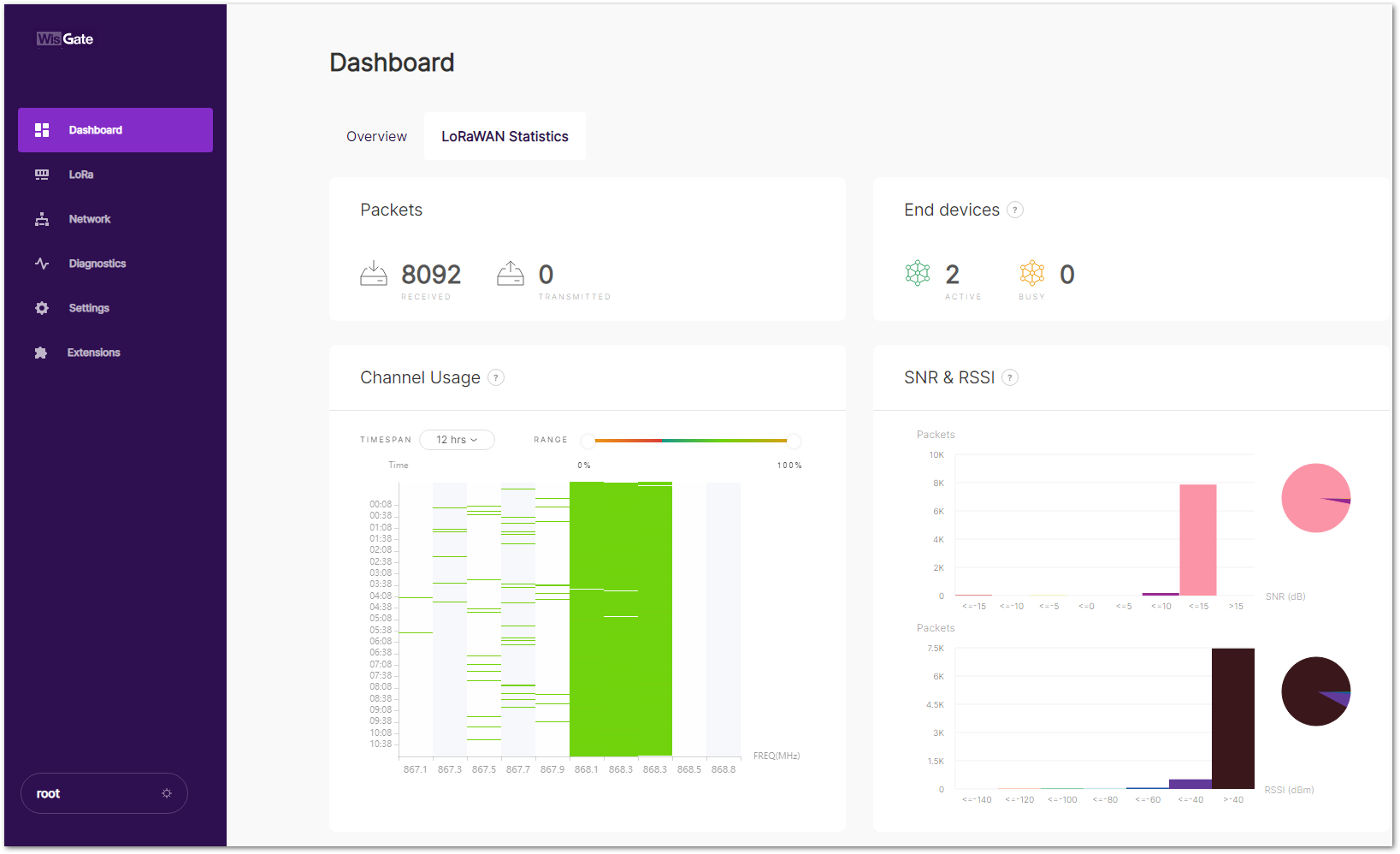 Figure 1: LoRaWAN statistics page
- For future logins, use the password you set. The default login username is root.
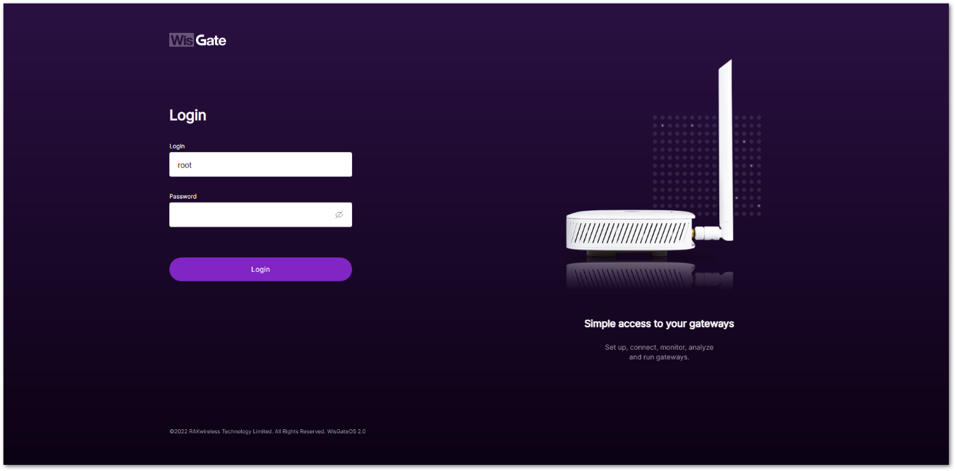 Figure 1: Login page with set password
WAN Port (Ethernet)
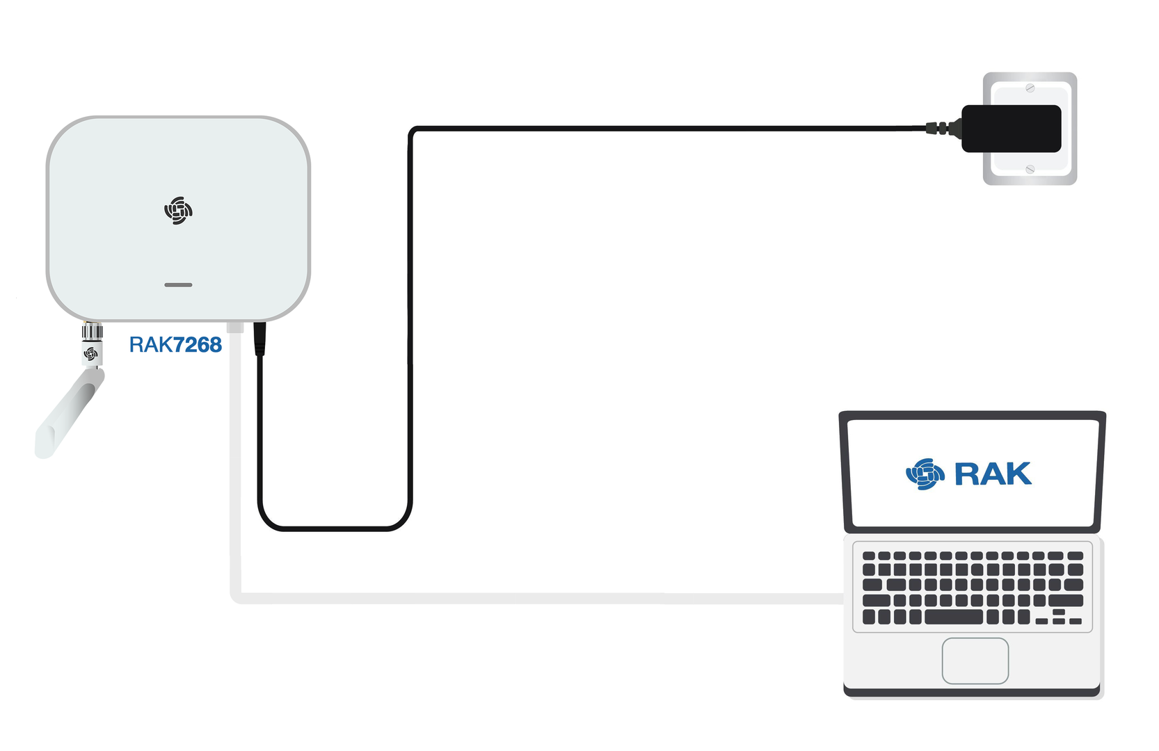 Figure 1: Accessing the gateway via WAN Port (Ethernet)
-
Connect the Ethernet cable from the gateway’s ETH(PoE) port to your PC’s Ethernet port.
-
Set a static IP address on your PC in the same subnet as the gateway:
NOTEThe default IP of the gateway is
169.254.X.X, derived from the last 4 bits of the MAC address. For example, if the last 4 bits are0F:01, the gateway IP is169.254.15.1. Set your PC's IP address accordingly, e.g.,169.254.15.100. -
Open the Internet Properties of your PC, and select Internet Protocol Version 4 (TCP/IPv4).
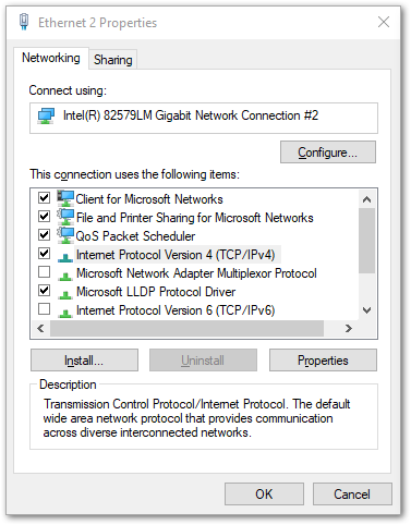 Figure 1: Internet properties
- Select Use the following IP address, and set the PC’s IP address (e.g.,
169.254.15.100). Ensure the PC’s IP address is in the same subnet as the gateway (e.g., if the gateway IP is169.254.15.1, set the PC to169.254.15.100).
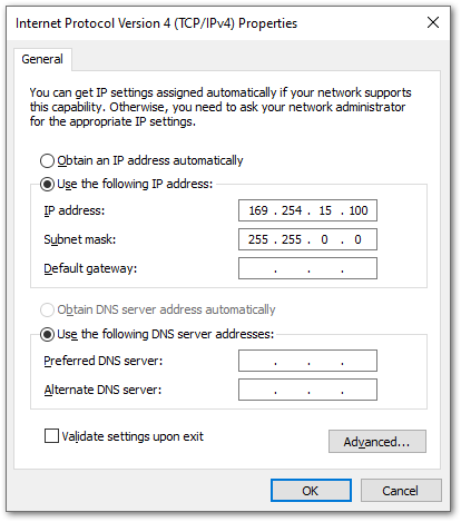 Figure 1: Setting IP address of the PC
In this example, you can access the gateway on the 169.254.15.1 address.
-
In a web browser, enter the gateway's IP (e.g.,
169.254.15.1) to access the Web UI. -
Set the login password following the same rules as in Wi-Fi mode.
-
After setting the password, the LoRaWAN Statistics page will load.
-
Use the username
rootand your password for future logins.
Access the Internet
You can connect the gateway to the internet through Wi-Fi, Ethernet, or LTE (for LTE models).
Connect Through Wi-Fi
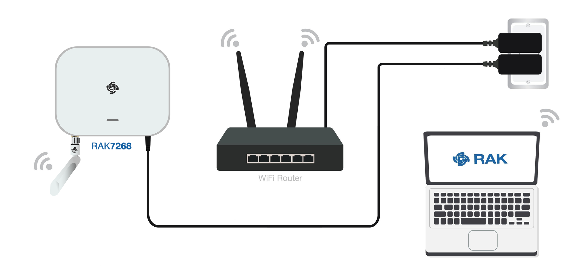 Figure 1: Connect the internet via Wi-Fi
-
Log in to the Web UI, go to Network > WAN > Wi-Fi.
-
Expand the Wi-Fi section and click on Settings. Ensure the Interface is enabled.
-
Click the Scan button to select your ESSID, or manually enter the ESSID of the network by clicking Enter network (E)SSID manually.
-
Choose the correct Encryption method and enter the appropriate Key.
NOTEAssuming you have entered the correct parameter values, you should receive an IP address assigned by your Wi-Fi router's (AP) built-in DHCP server. You can use this new IP address to log in via a web browser.
For details, refer to the WisGateOS 2 User Manual>WAN>Wi-Fi.
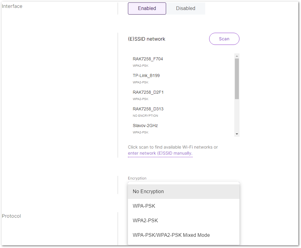 Figure 1: Wi-Fi settings
Connect Through Ethernet
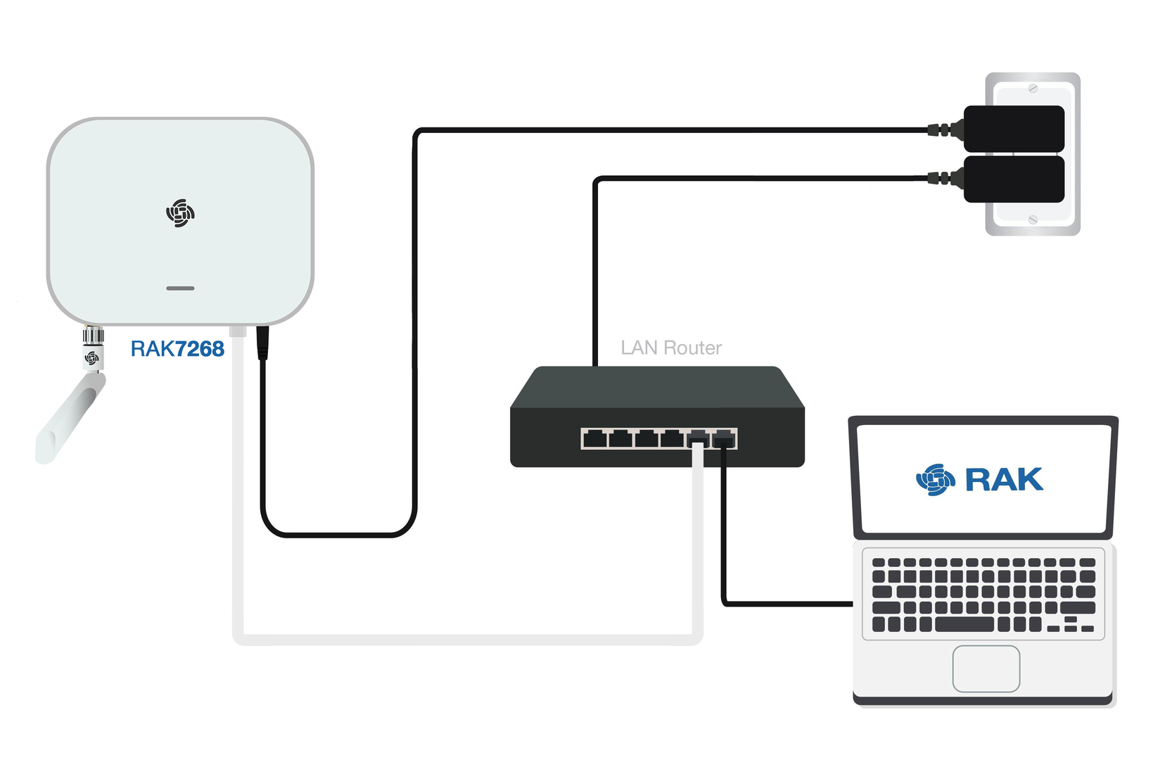 Figure 1: Accessing the Internet through Ethernet
- Connect one end of an Ethernet cable to the gateway’s ETH(PoE) port, and the other end to your router.
The router's DHCP server will automatically assign an IP address to the gateway. You can use this assigned IP to access the gateway via a web browser.
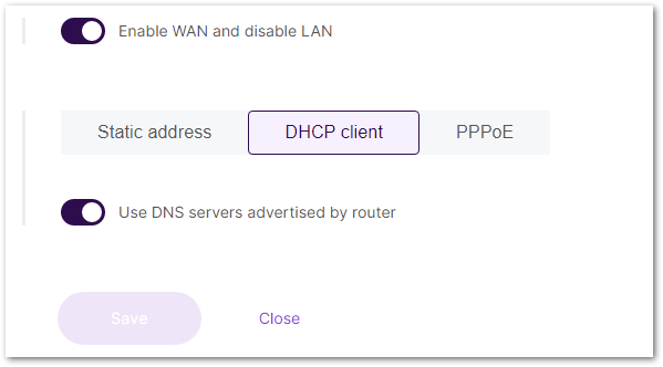 Figure 1: Connect through Ethernet settings
If additional configuration is required, refer to the WisGateOS 2 User Manual > WAN > Ethernet.
The gateway does not come with a PoE adapter by default. You can use one to power the gateway through Ethernet if needed, but it's optional.
Connect Through LTE (For LTE Version)
If your gateway supports LTE and you have inserted the SIM card, the gateway will automatically connect to the cellular network once the SIM card is inserted.
- If manual APN configuration is needed, go to Network > WAN > Cellular in the Web UI.
- Expand the Cellular section and click on Settings.
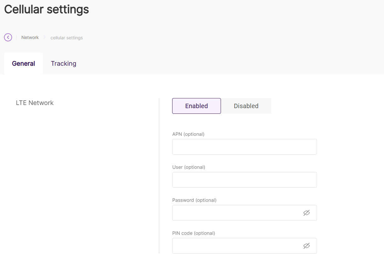 Figure 1: Connect through cellular settings
- For parameter configuration, refer to the WisGateOS 2 User Manual > WAN > Cellular.
Make sure that your SIM card is activated and supports data services. The gateway will use the LTE connection as a backup if the Wi-Fi or Ethernet connections are not available.
Tutorials
In this section, you can browse tutorials about the RAK7268V2/RAK7268CV2 gateway to help you better understand and use the product.