RAK9105U Smart Power Control LoRaWAN Network Server Guide
This guide shows how to connect RAK9105U to different LoRaWAN network servers.
Connect RAK9105U to RAK Built-in Network Server
- Start by accessing the gateway. Refer to the WisGateOS 2 user manual for detailed instructions.
 Figure 1: Login Page
- Once logged in, navigate to the LoRa menu and set the gateway's Work Mode to Built-in Network Server.
 Figure 1: Configure the Work Mode
- After setting the gateway to Built-in Network Server mode, navigate to the Applications tab.
 Figure 1: Applications Tab
- Click the Add Application button or the add one now link to create a new application. On the new page, fill in the following information:
 Figure 1: Add Application
- Application Name: Enter a name for the application.
- Application Description: Optionally, provide a brief description of the application.
- Application Type: Select the appropriate type from the drop-down menu.
- Unified Application Key: If enabled, all devices will use the same application key. This will reveal an Application Key field, where you must enter a key matching the one on the end device. You can either type the key manually or click Autogenerate to create one.
 Figure 1: Autogenerate Option
- After enabling the Auto Add Device option, configure the Application EUI. This value must match the node device. You can obtain it by querying the node device or modify the node’s corresponding value to match the automatically generated one.
- Once the Application EUI and Application Key are successfully verified, the device will be automatically added to the application.
 Figure 1: Auto Add Device Option
- Separate Application Keys: Each device will have its own unique application key, which must be added individually when registering the device.
-
Click Save application.
-
Head to the End Devices tab. If the Auto Add Device feature is enabled, devices should automatically register upon sending a join request.
 Figure 1: Device Added
If the Auto Add Device feature is not enabled, refer to the following steps to manually add devices.
- Click Add end devices.
 Figure 1: End Devices Tab
- On the End device information page fill in the following information:
 Figure 1: Add Device Manually
- Activation Mode: Select OTAA.
- End Device (Group) Name: Enter the name of the device.
- End Device Description (Optional): Optionally, add a description for the device.
- Class: Select the appropriate device class.
- Frame Counter Width: Use the default setting.
- LoRaWAN MAC Version: Select the correct LoRaWAN MAC version for the device.
- Click Add End Devices. On the Adding End Devices page, enter the Device EUI in the End Device EUI (Main) field and click Add to End Devices List.
 Figure 1: End Devices List
- If the EUI is correct, the device will appear in the End Devices list.
- If the EUI is incorrect, the device will appear in the End Devices list with an error message.
- Once the device is added to the End Devices List, click Add End Devices and confirm to proceed.
 Figure 1: Confirmation Message
- After completion, go to the End Devices interface to view the newly added device.
 Figure 1: Device Created
- Go back to the WisToolBox App, navigate to the Data on LoRa® Network tab, and click JOIN NETWORK. The device will connect to the network, as shown in Figure 13.
 Figure 1: Join Network
 Figure 1: Device Connected
The Things Network (TTN)
This section shows how to add a gateway and RAK9105U in the TTN network server. The following steps use the RAK gateway as an example.
Register the Gateway
- Log in to the TTNv3 website. If you already have a TTN account, use your The Things ID credentials to sign in.
 Figure 1: TTN Login Page
- To register a commercial gateway, go to the Gateways tab and click +Register Gateway.
 Figure 1: Register Gateway
- In the Gateway EUI field, enter the EUI of the gateway and click Confirm.
 Figure 1: Confirm Register
The gateway's EUI can be found on the sticker on the casing or by navigating to Dashboard > Overview in the Web UI. For instructions on accessing the gateway via Web UI, refer to the product's Quick Start Guide.
- After entering the EUI, click Confirm. Additional fields will appear. Fill in the following information:
 Figure 1: Fill in the Gateway Information
- To register the gateway, click Register gateway.
 Figure 1: Gateway registered
-
To generate a key file, click API Keys in the left navigation menu of the registered gateway.
-
On the API Keys page, click +Add API Key.
 Figure 1: Add API Keys
-
In the Name field, enter a name for the key (e.g., mykey).
-
Under Grant Individual Rights, select Link as Gateway to a Gateway for traffic exchange, i.e., write uplink and read downlink.
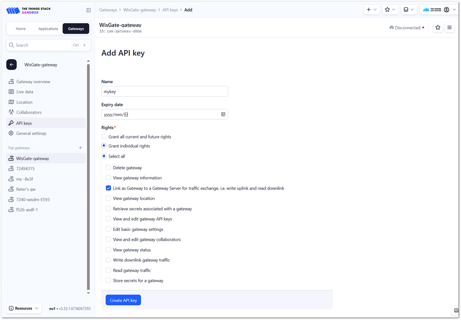 Figure 1: API Keys Options
- To generate the key, click Create API Key. A window will appear prompting you to copy the generated key. Click I have copied the key to proceed.
Copy the key and save it in a .txt file (or another secure location), as you won’t be able to view or copy it again later.
 Figure 1: Copy the API key
-
To configure the gateway, access it via the Web UI. For instructions, refer to the Quick Start Guide in the Gateway Documentation.
-
Navigate to LoRa > Configuration and set the following parameters. Then, save the changes.
 Figure 1: Configure Gateway
- Basics Station Server Type: Select LNS Server.
- Server URL: Enter the URL for The Things Stack server. For the European cluster, use:
wss://eu1.cloud.thethings.network - Server Port: Enter 8887 (the LNS Server port).
- Authentication Mode: Select TLS Server Authentication and Client Token. This will reveal the Trust (CA Certificate) and Client Token fields.
- Trust (CA Certificate): Upload the Let’s Encrypt ISRG ROOT X1 trust certificate by clicking Choose File. The certificate file can be downloaded directly.
- Client Token: Enter the previously generated API Key.
- To save the configuration, click Save Changes. If everything is configured correctly, the gateway will successfully connect to TTNv3.
 Figure 1: Gateway Connected
Register the End Device
- Click the Application tab in the left navigation menu to enter the application interface.
 Figure 1: Register End Device
- Click +Add application.
 Figure 1: Create Application
- After entering the application details, click Create Application to save the information.
 Figure 1: Applications Created
- Click +Register end device.
 Figure 1: End Device Parameters
- Input Method: Select Enter end device specifics manually.
- Frequency Plan: Choose the applicable frequency band.
- LoRaWAN Version: Select LoRaWAN Specification 1.0.3.
- JoinEUI: Enter the Application EUI, ensuring it matches the device. Click Confirm after entering.
- DevEUI: Enter the Device EUI, ensuring it matches the device.
- AppKey: Enter the Application Key, ensuring it matches the device.
- End Device ID: Enter a custom device ID.
- After filling the device details, click Register end device to save the information.
- Go back to the WisToolBox App, navigate to the Data on LoRa® Network tab, and click JOIN NETWORK. The device will connect to the network, as shown in Figure 29.
Figure 1: Join Network Figure 1: Device Connected
ChirpStack v4
This section shows how to add a gateway and RAK9105U in the ChirpStack v4 network server. The following steps will use the RAK gateway as an example.
ChirpStack v4 network server has been set up. For reference, follow RAK's guide on setting up the ChirpStack network server on AWS Cloud.
Register the Gateway
- To register the gateway in the ChirpStack network server, open a web browser and enter the server address of ChirpStack followed by port
8080.
<IP address of ChirpStack>:8080
-
Login using the following credentials:
- Username/email: admin
- Password: admin
 Figure 1: Chirpstack Login Page
- On the left pane, navigate to Gateways.
 Figure 1: Gateways List
- Click Add gateway.
 Figure 1: Add Gateway
- Name: Enter a unique name for the gateway on the network server. The name may only contain letters, numbers, and dashes.
- Description: Provide a brief description of the gateway.
- Gateway ID (EUI64): Enter the Extended Unique Identifier (EUI) of the gateway, which can be found in Dashboard > Overview of the gateway Web UI.
- Stats Interval (secs): Set the expected interval (in seconds) for the gateway to send its statistics.
- Click Submit. The registered gateway will appear in the Gateway List.
- To configure the gateway, access it via the Web UI. For detailed instructions, refer to the documentation of the selected gateway.
- Navigate to LoRa > Configuration, set the following parameters, and save the changes.
 Figure 1: Gateway Parameters
- Work Mode: Select Packet Forwarder.
- Protocol: Choose Semtech UDP GWMP Protocol.
- Server Address: Enter your ChirpStack server IP address.
- Server Port: The default port is
1700. If your ChirpStack server uses a different UDP port, ensure this value matches the server's UDP port configuration.
- Finally, click Save changes.
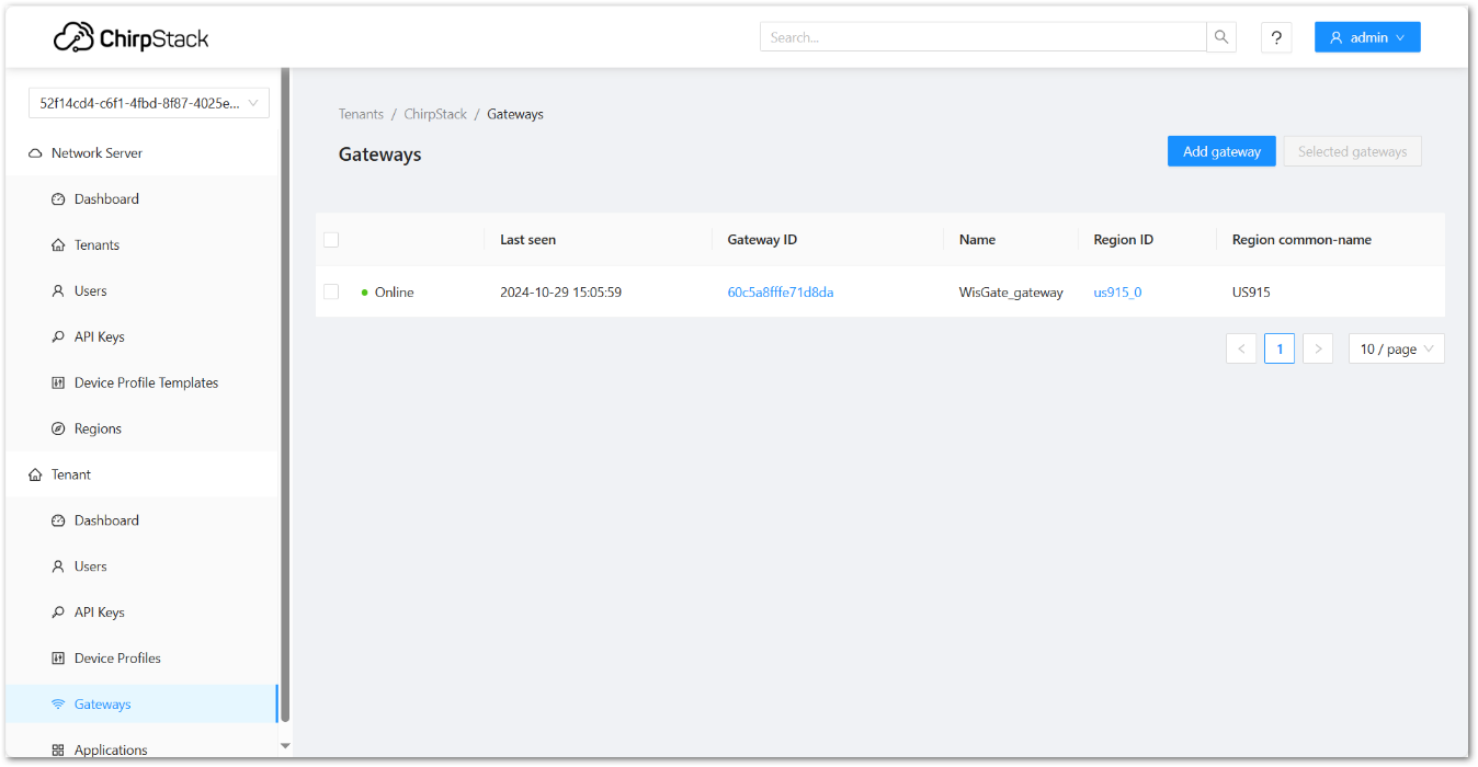 Figure 1: Gateway Parameters
Register the End Device
- On the left pane, navigate to Application.
 Figure 1: Select Applications
- Click Add application and configure the parameters.
 Figure 1: Select Applications
- Navigate to the Device Profiles tab and click Add Device Profile to create a new device profile.
 Figure 1: Select Applications
- In the General tab, configure the parameters.
 Figure 1: End Device Parameters
- Select the Class-C tab, enable Device supports Class-C, and Click Submit.
 Figure 1: Enable Class C support
- Navigate to the Applications tab and choose the newly created application. Click Add device.
 Figure 1: Applications Tab
- Add your new device and then click Submit.
 Figure 1: Add Device
- In the OTAA Keys section, configure the Application Key and click Submit.
 Figure 1: OTAA Keys
- Go back to the WisToolBox App, navigate to the Data on LoRa® Network tab, and click JOIN NETWORK. The device will connect to the network, as shown in Figure 44.
Figure 1: Join Network Figure 1: Device Connected
Data Analysis Examples
Power Interface Control
After RAK9105U joins the LoRa network server, you can send downlink commands from the server to RAK9105U to control the power switch of the connected device (Output3 or Output2). By default, 5 V Output3 and 12 V Output2 are both turned on.
| Command | Description |
|---|---|
| 0000 | 5 V Output3 Off |
| 0001 | 5 V Output3 On |
| 0100 | 12 V Output2 Off |
| 0101 | 12 V Output2 On |
The following operations take the built-in network server of the RAK gateway as an example for sending downlink commands.
- Click on the device information in the End devices list to enter the Configuration tab by default.
- Click the Downlink tab. Enter the port (customizable port number) and the command, then click Send.
 Figure 1: Downlink configuration
- After the command is successfully sent, check the command return in WisToolBox under ADVANCED > OPEN CONSOLE. At this point, the power output of Output2 on the RAK9105U has been turned off.
14:58 +EVT:RX_C:72:3:UNICAST:22:0100
14:58 [RX]:01 00
14:58 Turn off 12v output.
If the connected power supply device is a RAK outdoor gateway, the gateway may not power off immediately after the output power is turned off due to built-in capacitors.
Uplink Data
Setting Uplink Period
After the RAK9105U successfully joins the network, it will periodically send uplink data. You can set the uplink data transmission period by executing the following commands in the network server:
| Command | Description |
|---|---|
| 0201 | Uplink data period is 1 minute |
| 021E | Uplink data period is 30 minutes |
To set a specific uplink transmission period, execute the command ATC+SENDFREQ in the WisToolBox under ADVANCE > OPEN CONSOLE to set the uplink transmission period in minutes (1-1440 minutes).
The following operations take the built-in network server of the RAK gateway as an example for sending downlink commands.
- Click on the device information in the End devices list to enter the Configuration tab by default.
- Click the Downlink tab. Enter the port (customizable port number) and the command, then click Send.
 Figure 1: Downlink configuration
- After the command is successfully sent, check the command return in WisToolBox under ADVANCED > OPEN CONSOLE.
14:27 +EVT:RX_C:73:3:UNICAST:22:021e
14:27 [RX]:02 1e
14:27 The sending interval is set to: 30 minutes.
View Uplink Data
Whether it is connected to a 9~24 V external power supply or RAK Battery Plus, RAK9105U will periodically send uplink data to the server after it successfully joins the network.
The following operations take the built-in network server of the RAK gateway as an example for viewing the RAK9105U uplink data.
- Click on the device information in the End devices list to enter the Configuration tab by default.
- Click Packet capture to view the device's uplink data.
- Uplink data connected to an external 9~24 VDC
 Figure 1: Uplink data connected to an external source
- Uplink data connected to RAK Battery Plus
 Figure 1: Uplink data connected to RAK Battery Plus
Data Analysis
External Supply
In the application of an external 9~24 VDC power supply, after the device successfully joins the network, it will periodically send uplink data to the server.
Payload Data Description
The following Payload data is for example purposes only.
| Port: 1 | Payload: 0369 | ||||
|---|---|---|---|---|---|
| Data Type | Byte | Parameter | Raw Data | Parsed Data | |
| U8 | 1 Byte | Output Status | 03 | 5 Output ON 12 Output ON | |
| S8 | 1 Byte | 9105U SW Version | 69 | 1.0.5 | |
Output Status
| Status Code | Description |
|---|---|
| 00 | 5 V Output Off, 12 V Output Off |
| 01 | 5 V Output Off, 12 V Output Off |
| 02 | 5 V Output Off, 12 V Output Off |
| 03 | 5 V Output Off, 12 V Output Off |
RAK Battery Plus
Refer to the following data analyis to integrate custom applications for visual data display in the network server.
Payload Data Description
| Port: 2 | Payload: 0555fff700100c4c3f | ||||
|---|---|---|---|---|---|
| Data Type | Byte | Parameter | Raw Data | Parsed Data | Unit |
| U8 | 1 Byte | Cur voltage | 0555 | 1365 | 0.01 V |
| S8 | 1 Byte | Cur current | fff7 | -9 | 0.01 A |
| U8 | 1 Byte | Cycle times | 0010 | 16 | Times |
| U8 | 1 Byte | Remain capacity | 0c4c | 3148 | 10 mAh |
| U8 | 1 Byte | Cur soc | 3f | 63 | 1% |
| Port: 3 | Payload: 138800000000000002 | ||||
|---|---|---|---|---|---|
| Data Type | Byte | Parameter | Raw Data | Parsed Data | Unit |
| U8 | 1 Byte | Full capacity | 1388 | 5000 | 10 mAh |
| U8 | 1 Byte | Cust fault status H | 0000 | Normal Data description can be found in the Errors H. | - |
| U8 | 1 Byte | Cust fault status L | 0000 | Normal Data description can be found in the Errors L | - |
| U8 | 1 Byte | Cust warn status H | 0000 | Normal Data description can be found in the Warnings H | - |
| U8 | 1 Byte | Battery Mode | 02 | Discharging Data description can be found in the Battery Mode. | - |
| Port: 4 | Payload: 10101064A403680101 | ||||
|---|---|---|---|---|---|
| Data Type | Byte | Parameter | Raw Data | Parsed Data | Unit |
| U8 | 1 Byte | Average temp | 10 | 16 | 1° C |
| U8 | 1 Byte | Max temp | 10 | 16 | 1° C |
| U8 | 1 Byte | Min temp | 10 | 16 | 1° C |
| U8 | 1 Byte | Cur soh | 64 | 100 | 1% |
| U8 | 1 Byte | Battery status | A4 | - | |
| U8 | 1 Byte | Output status | 03 | 5 V Output On 12 V Output On Data description can be found in the Output Status | - |
| U8 | 1 Byte | 9105U SW Version | 68 | 1.0.4 | - |
| U8 | 1 Byte | BMS Boot Version | 0101 | 1.01 | - |
Output Status
| Status Code | Description |
|---|---|
| 00 | 5 V Output Off, 12 V Output Off |
| 01 | 5 V Output On, 12 V Output Off |
| 02 | 5 V Output Off, 12 V Output On |
| 03 | 5 V Output On, 12 V Output On |
Battery Mode
| Status Code | Description |
|---|---|
| 0 | Null |
| 1 | Charging |
| 2 | Discharging |
| 3 | Fully Charged |
| 4 | Fully Discharged |
| 5 | Protect |
| 6 | Permanent fail |
| 7 | Null |
Errors H
| Bit | Description | Status |
|---|---|---|
| Bit0 | Battery under voltage protect | 0: normal |
| Bit1 | Discharge over current protect | 0: normal |
| Bit2 | Discharge low temperature protect | 0: normal |
| Bit3 | Discharge low temperature protect | 0: normal |
| Bit4 | Discharge short circuit protect | 0: normal |
| Bit5 | Discharge over current lock | 0: normal |
| Bit6 | Over voltage protect | 0: normal |
| Bit7 | Charge over current protect | 0: normal |
| Bit8 | Charge low temperature protect | 0: normal |
| Bit9 | Charge high temperature protect | 0: normal |
| Bit10 | Charge short circuit protect | 0: normal |
| Bit11 | Charge over current lock | 0: normal |
| Bit12 - Bit15 | Reserved | 0: normal |
Errors L
| Bit | Description | Status |
|---|---|---|
| Bit0 | Voltage sampling AFE (analog front end) error | 0: normal |
| Bit1 | Parameter configuration error | 0: normal |
| Bit2 | Discharge MOS error | 0: normal |
| Bit3 | Charge MOS error | 0: normal |
| Bit4 | Voltage sampling line break error | 0: normal |
| Bit5 | Temperature sampling line break error | 0: normal |
| Bit6 | Reserved | 0: normal |
| Bit7 | Balancing circuit error | 0: normal |
| Bit8 | Reserved | 0: normal |
| Bit9 | MOSFET temperature above normal | 0: normal |
| Bit10 | Reserved | 0: normal |
| Bit11 | Reserved | 0: normal |
| Bit12 - Bit15 | Reserved | 0: normal |
Warnings H
| Bit | Description | Status |
|---|---|---|
| Bit0 | Under voltage warning | 0: normal |
| Bit1 | Over voltage warning | 0: normal |
| Bit2 | Discharge over current warning | 0: normal |
| Bit3 | Charge over current warning | 0: normal |
| Bit4 | Discharge low temperature warning | 0: normal |
| Bit5 | Discharge high temperature warning | 0: normal |
| Bit6 | Charge low temperature warning | 0: normal |
| Bit7 | Charge high temperature warning | 0: normal |
| Bit8 | Fully charged warning | 0: normal |
| Bit9 | Reserved | 0: normal |
| Bit10 | Reserved | 0: normal |
| Bit11 | MOS high temperature warning | 0: normal |
| Bit12 | Reserved | 0: normal |
| Bit13 | Reserved | 0: normal |
| Bit14 | Reserved | 0: normal |
| Bit15 | Low SOC waring | 0: normal |