RAK9105U Smart Power Control Quick Start Guide
Prerequisites
Before going through each and every step in the installation guide of the USB Power Convertor, make sure to prepare the necessary items listed below:
Hardware
- RAK9105U USB Power Convertor
- 9~24 V external DC power supply
- RAK Battery Plus
- 9~24 V external DC power supply
- Gateway in range
- A Windows/macOS/Linux Computer
Software
Package Inclusions
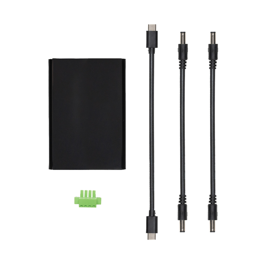 Figure 1: RAK9105U Package Inclusions 1
- One (1) RAK9105U USB Power Convertor
- One (1) USB Type-C Cable
- Two (2) DC Cables
- One (1) 4-Pin Terminal Block
Installation
Based on different application scenarios, the power input and device installation for RAK9105U are different.
Smart Power Control Applications
In this application scenario, the RAK9105U is integrated between the power supply and the power distribution device. By configuring its power output interface, it controls the power switch of connected distribution devices, such as gateways, CPE devices, routers, and other equipment.
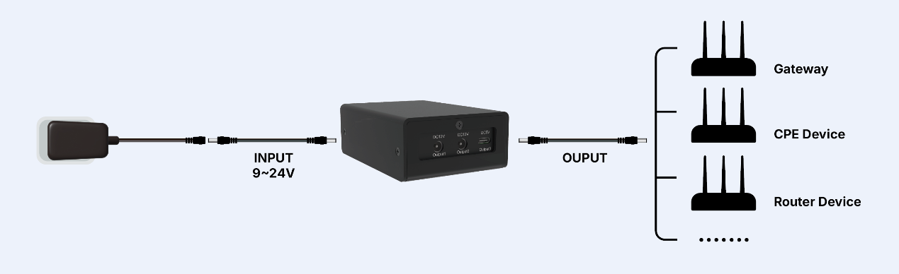 Figure 1: Power Supply Installation
Device Connection
- Connect the power input interface of the device (such as gateways, CPE devices, routers, etc.) to the Output2 interface of the RAK9105U using a DC cable.
- Connect an external power supply (9–24 V) to the Input DC 12 V interface of the RAK9105U using the provided DC cable.
- Enable the external power supply to power the RAK9105U.
- When connecting a device to the RAK9105U, use appropriate cables that match the device's power interface.
- The above steps use the Output2 interface as an example. Select the appropriate power output interface of the RAK9105U based on the device’s actual input voltage range. For details, refer to - Output Interfaces.
RAK Battery Plus Data Monitoring and Power Control Application
In the application of the RAK Battery Plus integrating the RAK9105U, it not only monitors the battery's operational status but also enables remote power control for the gateway or other devices connected to the RAK9105U's power output interface.
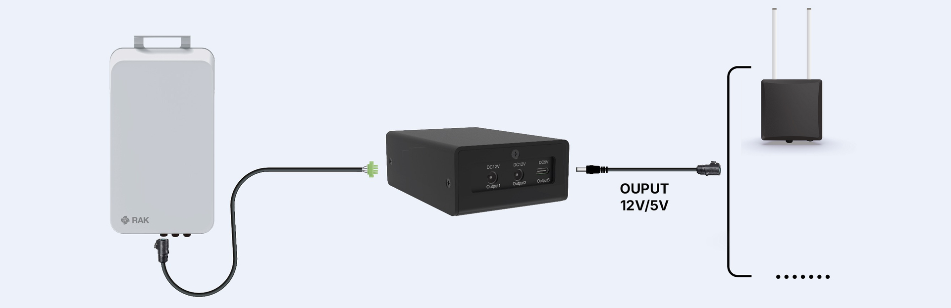 Figure 1: RAK Battery Plus connection
Device Connection
For Battery Plus installation, refer to the product documentation.
- Connect the power interface of the device (gateway or other devices) to the Output2 interface of the RAK9105U.
- Connect the cable used by the RAK Battery Plus to the 4-pin terminal block.
- Refer to the interface labels and correctly insert the cable with the 4-pin terminal block into the Input DC12 V RS485 interface of the RAK9105U.
- Press the power switch (ON/OFF) on the side of the RAK Battery Plus to turn it on.
- When connecting a device to the RAK9105U, use appropriate cables that match the device's power interface.
- The above steps use the Output2 interface as an example. Select the appropriate power output interface of the RAK9105U based on the device’s actual input voltage range. For details, refer to Output Interfaces.
Device Configuration
Connect the RAK2461 to WisToolBox
- Download and install the WisToolBox.
- Connect the RAK9105U to the PC via the Console interface using a Type-C USB cable.
- Launch WisToolBox and click CONNECT DEVICE.
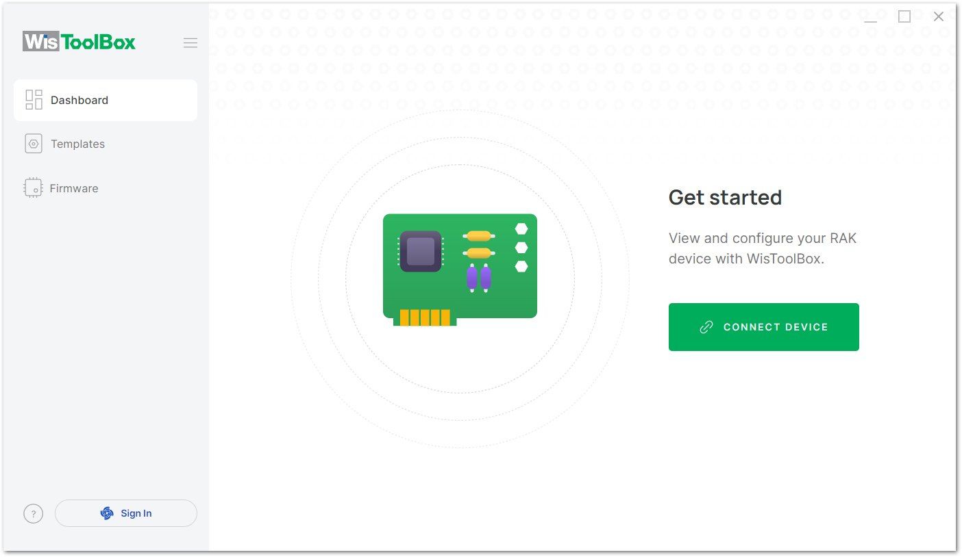 Figure 1: Connect Device
- After the device is found, check the device information and click CONNECT.
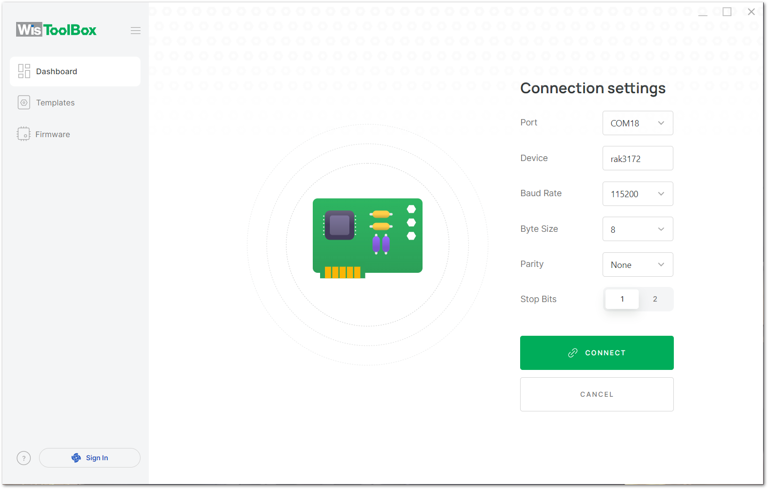 Figure 1: Device Details
- The control of the RAK9105U is managed by the RAK3172, which will appear as the core device in WisToolBox. Click on it.
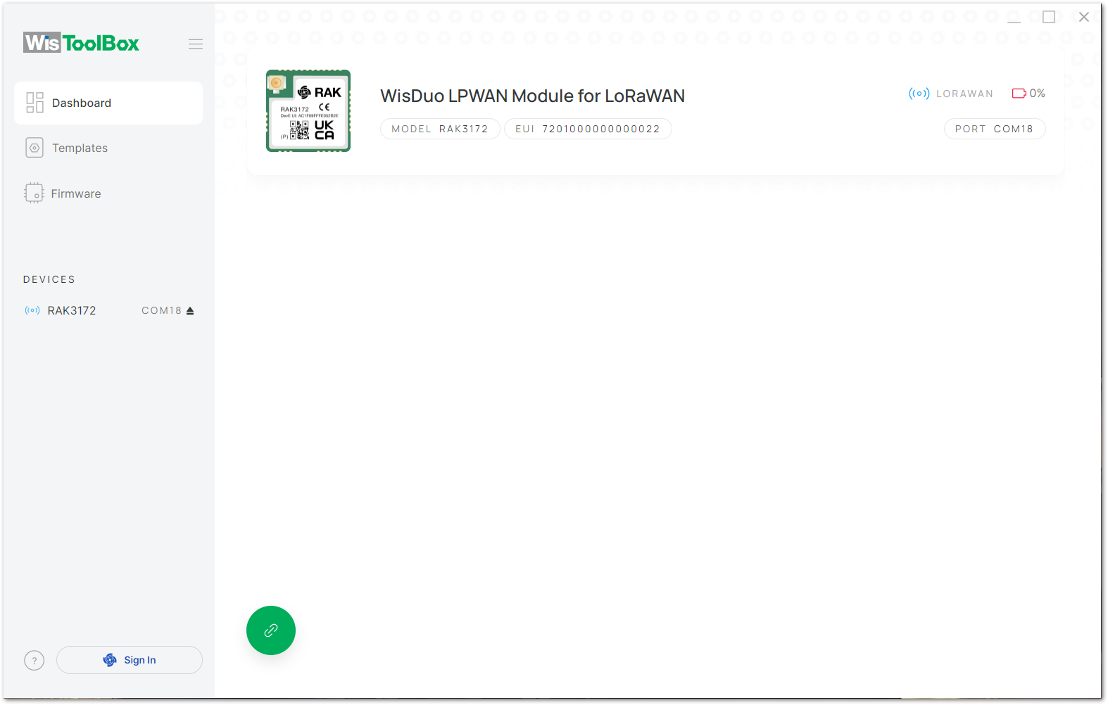 Figure 1: Select Device
RAK9105U Network Configuration
- Go to the PARAMETERS tab and configure the network parameters for the device.
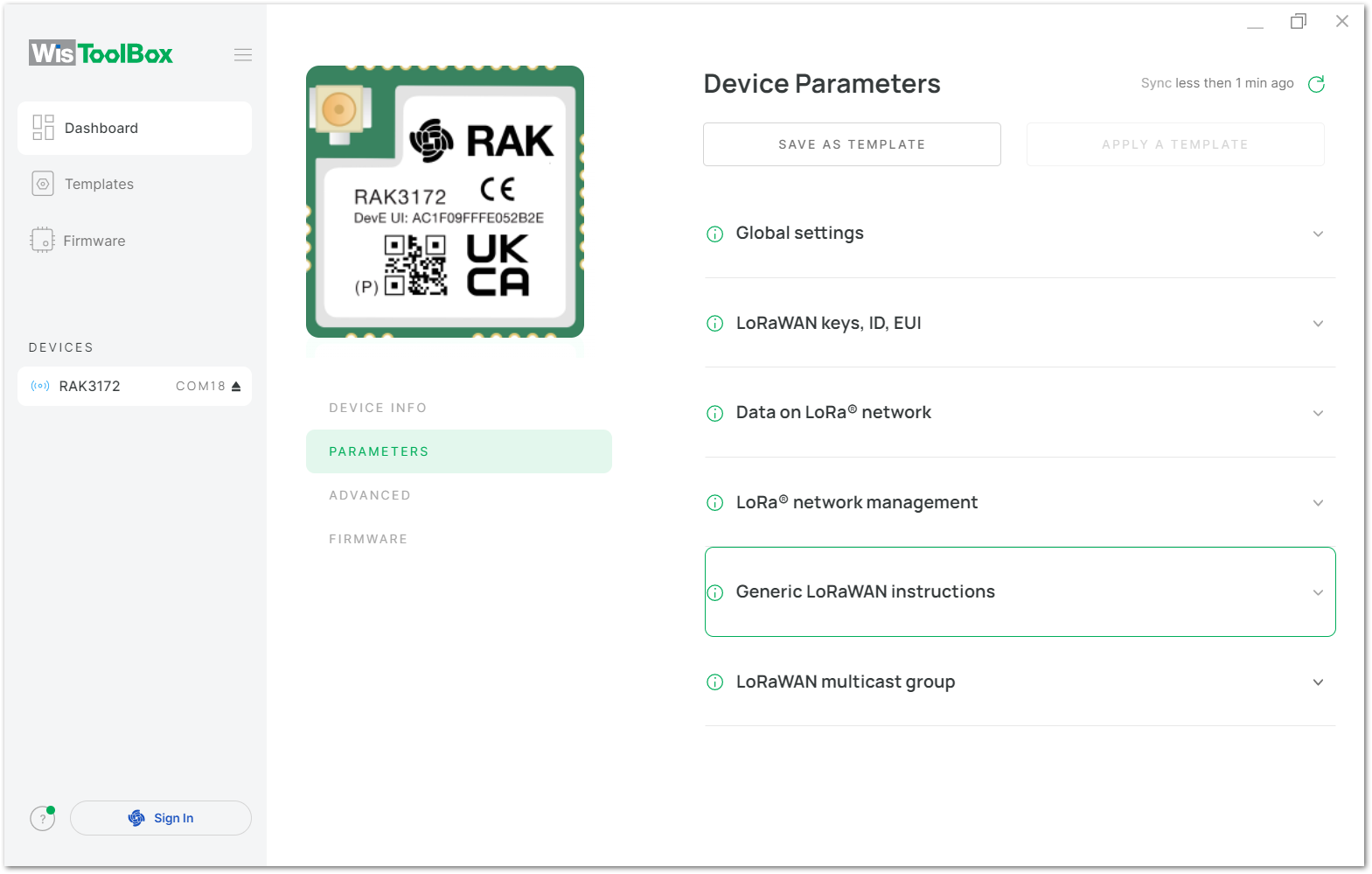 Figure 1: Device Parameters
- Click on the Global Settings option and configure the following parameters:
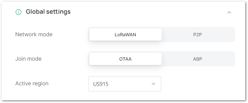 Figure 1: Global Settings
- Network Mode: Select LoRaWAN mode.
- Join Mode: Select OTAA (this device only supports OTAA).
- Active Region: Choose the frequency used by the device, ensuring it matches the gateway frequency band of the deployed LoRaWAN® network.
- Click on the LoRaWAN keys, ID, EUI option to view or modify the device's information.
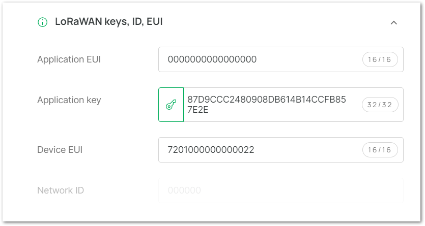 Figure 1: LoRaWAN keys, ID, and EUI
- Application EUI: Modify the Application EUI.
- Application Key: Manually modify it or click the Generate Application Key icon to automatically generate a key.
- Device EUI: Modify the Device EUI.
- Click on the Data on LoRa® network option to configure the device's network settings.
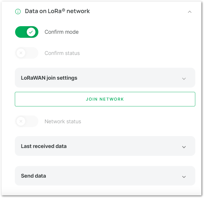 Figure 1: Data on LoRa Network
- Confirm Mode: Set the message confirmation mode.
- Confirm Status: Check or modify the message confirmation status.
- Enable Join Process: Enable network joining.
- Automatic Access: Choose whether the module should automatically joins the network upon powering on.
- Reattempt Period (s): Set the network retry period (7–255 seconds, default: 8).
- Max Number of Reattempts: Define the maximum number of retries (0–255, default: 0).
- JOIN NETWORK: If Automatic Access is disabled, click this button to manually join the network.
- Network Status: Displays as enabled after successful network access.
- Last Received Data: View the most recently data received by the device.
- Send Data: Configure the port number and send uplink data to the gateway.
- Click APPLY COMAND in the Command pop-up window to apply the updated configuration information to the device.
 Figure 1: Apply Commands
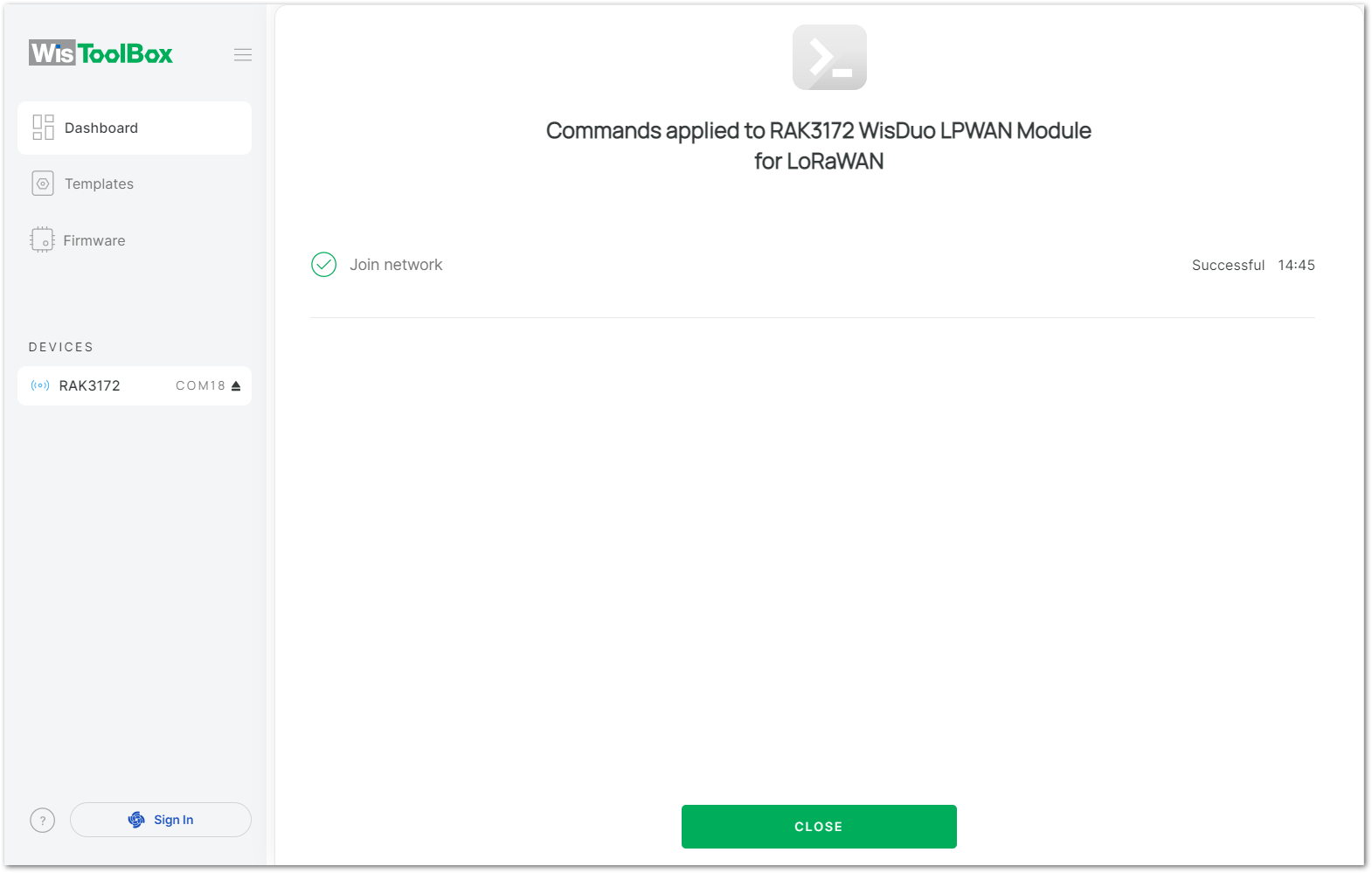 Figure 1: Commands Applied